Download
1 / 13
130 likes | 212 Views
OMEGA DATA CUBE ORBNNNN_M.QUB. sdat0. sdat1. Idat S jdat. OMEGA GEOMETRY CUBE (ORBNNNN_M.NAV). Bands 0-20: SWIR-C (All angles in units of 0.0001°) 2: incidence wrt reference ellipsoid 3: emergence wrt reference ellipsoid 4: incidence wrt center of Mars

E N D
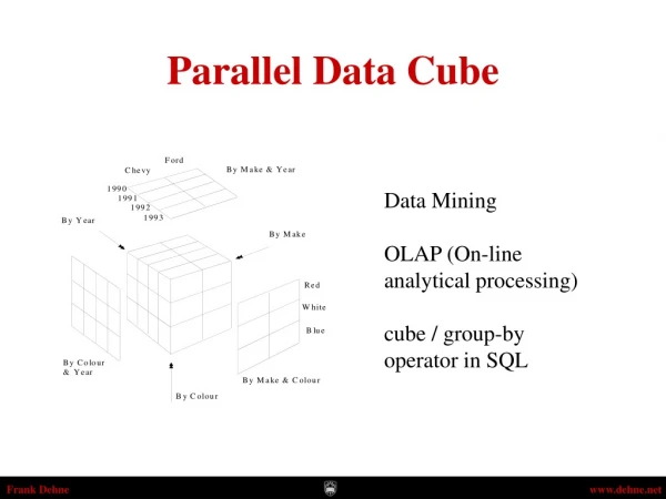
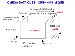
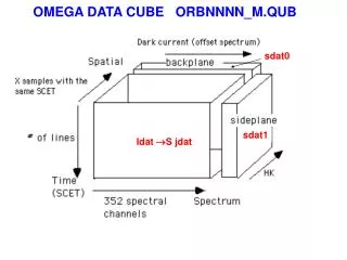
OMEGA DATA CUBE ORBNNNN_M.QUB sdat0 sdat1 Idat S jdat
OMEGA GEOMETRY CUBE (ORBNNNN_M.NAV) Bands 0-20: SWIR-C (All angles in units of 0.0001°) 2: incidence wrt reference ellipsoid 3: emergence wrt reference ellipsoid 4: incidence wrt center of Mars 5: emergence wrt center of Mars 6: longitude of the pixel center 7: latitude of the pixel center 8: incidence wrt the local normal (MOLA) 9: emergence wrt the local normal 10: phase wrt the local normal 11: slant distance (meters) 12: MOLA elevation (meters) 13-16: longitude of the 4 corners 17-20: latitude of the 4 corners Bands 21-35: same as 16-20 for SWIR-L Bands 36-50: same as 16-20 for VIS geocube First cut at positioning. Can be off by
THE OMEGA REDUCTION SOFTWARE (IDL) • provided as a ZIP file in the SOFTWARE directory (present revision: SOFT04.ZIP) • unzipping the latest ZIP file creates a subdirectory SOFTNN • all files from the SOFTNN subdirectory must be copied to the working directory • A users’ guide and information on updates is provided in SOFTNN_readme.txt • omega_path must be edited so as to point to the proper directories • for the QUB and NAV files respectively (which can be the same) • the path must end with a \ for windows, with a / for linux • a QUB file and its NAV file can then be read by typing: • IDL (CR) • IDL>.run readomega (CR) • OMEGA observation: ORBNNNN_M(CR) (name without the extension) • readomega compiles required procedures, then creates the following arrays • idat: raw data sdat0: dark current and offset • jdat: radiance sdat1: housekeeping info • specmars: solar spectrum ( I/F) wvl: table of wavelengths • geocube: geometry information mtf: photometric function • exposure: 3 values (C, L, Vis) summation: co-added successive scans • detailed information on the content of these arrays is provided in the EAICD • (/doc repertory in PSA)
OMEGA DATA SET AND ARCHIVE • Access through the Planetary Science Archive • at ESTEC with a mirror in the PDS data base • increasing numbers of bad pixels with time (see next talk) • The data and tools available to the « wide science community » • are those available to CoI’s during the proprietary period • Basic policy : • - no « final truth » calibrated data set (level 2) • - level 1B is the prime data set, with associated geometry cubes • (for each pixel: longitude, latitude, incidence, emergence, phase, • distance, MOLA altitude) • - reduction software to level 2 is provided (IDL)
Main derived variables of interest (see EAICD for details) Radiance factor: jdat(*,k,*)/specmars(k) for k=0,351 Cos(incidence): cos(geocube(*,2,*)*1.e-4*!dtor) Reflectance factor: Radiance factor / cos(incidence) Distance along LOS: geocube(*,10,*)*1.e-4 MOLA altitude: geocube(*,11,*)*1.e-4 MOLA local incidence: cos(geocube(*,8,*)*1.e-4*!dtor) Center longitude: geocube(*,6,*) * 1.e-4 (C channel) Center latitude: geocube(*,7,*) * 1.e-4 (C channel) Geometry restitution by Nicolas Manaud when he was at IAS Relative positionning is very good for 16, 32 and 64 pixel modes. A small correction is needed for 128 pixel modes, it will be Included in a future release Absolute positioning can be off by several km (1 sec along track: 4 km at pericenter) Repositioning the cube is required
REPOSITIONNING A CUBE • agreed upon referential for Mex: IAU 2000 (East longitudes) • available information: • MOLA derived variables (geocube): altitude, local incidence • Viking HR mosaic (MAPPS) • MGS image data set • in progress: MRO data • already available in the data set: MOLA altitude and local incidence • local_light_level=cos(geocube(*,8,*)*!dtor*1.e-4) • a map of this variable is expected to match the albedo map • at wavelengths < 3.5 µm (no thermal contribution) • if the region is spectrally grey
I/F (1.3 µm)cos(local inc.) Example from orbit 1254_3 applying correlation methods makes it possible to reposition the I/F map relative to MOLA within a fraction of a pixel the same process is required for each channel I/F (1.3 µm)cos(local inc.) I/F (1.3 µm) shift by 2 pixels left and 1 pixel down
EVOLUTION OF THE L CHANNEL (128 to 255, 2.53 µm to 5.1 µm) • Internal cal level is very stable for the C channel • variations by more than a factor of 2 • for the L channel over 1 year of operations • lesser impact for the signal from Mars • the photometric function for the L channel • applies only to high level regions (close • to ground calibration levels): • orbits 0018 to 0500 • orbits 0905 to 1206 Level of internal cal, spectel 102 (green, C) and 165 (red, L) • the C to L angular distance • (nominally ~ 1 pixel = 1.2 mrad) • increases up to 3 mrad (nearly 3 pixels) • for low levels of the internal calibration • C to L co-registration is required so as to • obtain a reliable full spectrum • common reference: MOLA DTM (provided • in geocube) C to L angular distance / level of the internal cal
Co-registering the three channels: cube 1254_3 VIS channel I/F at 0.69 µm L channel I/F at 3.52 µm C channel I/F at 1.30 µm shift by 5 pixels right shift by 4 pixels down shift by 2 pixels down the elongated PSF of the VIS channel impacts the spatial resolution
co-registration of channels, cube 18_01 0.69 µm 1.30 µm 3.51 µm solar longitude : Ls 333° (late southern summer) aerosols: Optical thickness ~ 1 In the visible decreases with wavelength: Improving contrast black: 0.5 max, white: max
SCANNING PROBLEMS AT 128 PIXELS WHEN THE SCANNER IS TOO COLD (< -15 C) anomalous scan Normal scan scan 171 has a problem Scan position, pixel 2, 128 pixel mode, cube 1354_3
SCANNER WARM-UP CUBES • a solution to this problem consists in operating the scanner • in a “safe” mode (64 pixels) so as to heat it up • warm-up 64 pixels cubes are always labeled “NNNN_0” • (only when before a 128 pixel cube, some are fully OK) • they are stored with high compression (1 bit/data) • they can include the last stages of detector cooling • litmus test for using “NNNN_0” cubes: check detector temperatures • “C” detector: sdat1(0,2, j) where j is the number of the scan • “L” detector: sdat1(1,2, j) where j is the number of the scan • Units: 0.001 °C. Valid temperatures: < -190 °C
CONCLUSIONS • the positioning information provided by SOFTNN is reliable • as a first indication. If it goes wild, this is real (the scanner • is oscillating at high frequency) • fine tuning is needed for each channel. Accurate positioning • at sub-pixel levels can be achieved by comparing with • MOLA slopes, altitudes. • the offset between the C channel and the L channel • depends on the status of the instrument, which can be • inferred from the level of the calibration lamp