Download
1 / 17
350 likes | 1.55k Views
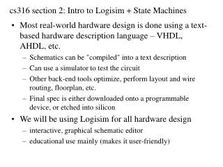
Logisim. HDL language and Logisim. Most real-world hardware design is done using a text-based hardware description language – VHDL, Verilog, etc. Schematics can be compiled into a text decription Can use a simulator to test the circuit

E N D
HDL language and Logisim • Most real-world hardware design is done using a text-based hardware description language – VHDL, Verilog, etc. • Schematics can be compiled into a text decription • Can use a simulator to test the circuit • Other back-end tools optimize, perform layout and wire routing, floorplan, etc. • Final spec is either downloaded onto a programmable device, or etched into silicon. • We will use Logisim for all hardware design • Interactive, graphical schematic editor • Educational use, user-friendly
Other CAD tools in circuit design • Circuit level tool vendors • Cadence, Synopsys, etc. • other smaller players • Board level tool vendors • Altium, Eagle and many more
HDL language and Logisim • Most real-world hardware design is done using a text-based hardware description language – VHDL, Verilog, etc. • Schematics can be compiled into a text decription • Can use a simulator to test the circuit • Other back-end tools optimize, perform layout and wire routing, floorplan, etc. • Final spec is either downloaded onto a programmable device, or etched into silicon. • We will use Logisim for all hardware design • Interactive, graphical schematic editor • Educational use, user-friendly
To be covered… • Pins and subcircuits • Probes for debugging • Bundles/splitters • Logging • Test vectors • S-R latch, D latch, D flip-flop • Examples
Example Circuit: 1 bit 2:1 Mux • S = P if R == 0 • S = Q if R == 1
Subcircuits: 2:1 Mux and Controller • S = Q if R == 010 • S = P otherwise
Logging and Test Vectors Test Vector Truth Table Log File
Logisim Don’ts • Leave wires floating • Works in logisim • Breaks in real life • Use a multiplexor instead of controlled buffer
LogisimDon’ts (cont.) • Don’t reinvent the wheel • Waste time • Confusing to grade • Almost every component is customizable • Number of inputs • Input bit width
Logisim Don’ts (cont.) • Avoid Constant input • Constants are almost never necessary • Exception is supplying value to extra input • Try to optimize away before using • Truth table
Logisim Don’ts (cont.) • Don’t make trivial subcircuits • Sub-circuit needs to perform some meaningful logic functions • You will never have a C function just to add two numbers up, do you? • Problems • Wasting time specifying inputs and outputs of small circuits • Big hierarchy hard to understand
Logisim Don’ts (cont.) • Don’t use invisible splitters • All you really need is just a wire • It is really hard to see them when we grade
Logisim Don’ts (cont.) • Don’t work from Right to Left
Some more information • MIPS assignment: • 32-bit ALU • 32-bit pipelined processor • Looking for help? • Course webpage http://www.cs.cornell.edu/courses/cs3410/2011sp/ • Newsgroup: cornell.class.cs3410 • Staff email list: cs3410-staff-l@cs.cornell.edu