Download
1 / 18
180 likes | 280 Views
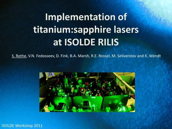
Implementation of titanium:sapphire lasers at ISOLDE RILIS. S. Rothe , V.N. Fedosseev , D. Fink, B.A. Marsh, R.E. Rossel , M. Seliverstov and K. Wendt. ISOLDE Workshop 2011. Outline. The RILIS principle The new solid- state laser system RILIS operation 2011

E N D
Implementation of titanium:sapphire lasers at ISOLDE RILIS S. Rothe, V.N. Fedosseev, D. Fink, B.A. Marsh, R.E. Rossel, M. Seliverstovand K. Wendt ISOLDE Workshop 2011
Outline • The RILIS principle • The new solid-statelasersystem • RILIS operation 2011 • In-sourcelaserspectroscopyofAstatine
The ResonanceIonization Laser Ion Source (RILIS) Laser ionization scheme Laser Ion Source laser beams line target • Simple setup at target site: same as surface ion source • RILIS lasers excite and ionize atoms At Z selective Laser tuned to Z = 85 Isotope of interest 205At Magnet set to A = 205 Auto-ionizing State Ionization potential Rydberg State Excited States Ground State
The RILIS dye lasers Pump laser: Nd:YAG (532 nm) Repetition rate: 10 kHz, Pulse duration: 9ns Power: 100 W dye lasers: 2 x broadband (6 GHz) 1 x narrow band (1 GHz) After CVL removal 2010 Laser table Jan. 2011 > 10 different dyes used
RILIS operation 1994 to 2010 demand Realistic curve for one laser system
SPES ALTO RIKEN Laser ion sources World-Wide ? hot cavity ? ? hot cavity ? ? gas catcher ? ORNL OakRidge(off-line) hotcavity rep. rate ~10 kHz ti:salaser LISOL Louvain-la-Neuve gas cell rep. rate <200Hz dye laser RISIKO GISELE FURIOS RILIS • Mainz (off-line) rep. rate ~10 kHz ti:salaser • Caen (off-line) rep. rate ~10 kHz ti:salaser Jyväskylä gas cell rep. rate ~10 kHz ti:sa & dyelaser ISOLDE, Geneva hot cavity rep. rate 10 kHz dye laser TRILIS PNPI Vancouver hotcavity rep. rate ~10 kHz ti:salaser Gatchina hot cavity rep. rate ~10 kHz dye laser TIARA Takasaki hot cavity rep. rate 300Hz dye laser Selectiononly. updatedfrom C. Geppert (2007) V.Fedosseev (2010)
Comparison dye vs. Ti:Sasystem Dye Ti:Sa 2x Dye 2x Ti:Sa Ti:Sa 3x Ti:Sa 3x Dye 4x Ti:Sa Dye Ti:Sa system is complementary
The Ti:Salaser • Lasing medium: • solid-state Ti doped sapphire (Ti:Al2O3) • Hardness 9 birefringent tuner etalon end mirror laser crystal Serial production • 3d model • Mainz-Type • Design optimized for on-line operations output coupler pump beam • Prototype • Machined at Mainz University workshop • Serial production • 3 Ti:Sa modules available
The RILIS Ti:Salasers Pump laser: Nd:YAG (532 nm) Repetition rate: 10 kHz Pulse length: 180 ns Power: 60 W Change of mirror sets in resonator No amplifier yet available No ageing 100 mm Ti:Sa lasers: Line width: 5 GHz Pulse length: 30-50 ns • Wavelength tuning range: • Fundamental (w) 690- 940nm (5 W) • 2nd harmonic (2w) 345- 470nm (1 W) • 3rd harmonic (3w) 230- 310nm (150 mW) • 4th harmonic (2w) 205-235 nm (50 mW) 6 resonator mirrorsets cover the Ti:Sa range
Dye RILIS Nd:YAG Dye 2 l–meter SHG Dye 1 THG 10 kHz Master clock NarrowbandDye RILIS Dye Laser System GPS/HRS Target & Ion Source
Ti:Sa & DyeRILIS Nd:YAG Dye 2 l–meter SHG Dye 1 THG 10 kHz Master clock NarrowbandDye RILIS Dye Laser System GPS/HRS Delay generator RILIS Ti:Sa Laser System Target & Ion Source Nd:YAG Ti:Sa 1 SHG/THG/FHG Ti:Sa 2 Faraday cup… Ti:Sa 3 l–meter LabVIEWbased DAQ pA – meter
RILIS operation 2011 Ti:Sa involvement • Ion beams of 16 elements were produced since beginning of the running period: • 2573 h for on-line experiments • Ti:Sa system used already with 9 elements • Some additional tests only feasible because of the ‘spare’ laser system
New modes of operation – The Dual RILIS Condition for dual operation: Temporal synchronization of the two laser systems Backup mode dye and Ti:Sa are exchangeable Ti:Sa only mode 100 W Nd:YAG laser available for non-resonant ionization Mixed mode Combination of dye and Ti:Sa Reduction in down time New RILIS elements Highest efficiencies
At in-sourcespectroscopy a) Photoionization threshold : 75129(95) cm-1 b) Scan for 2nd step transitions (at TRIUMF) c) Verification of levels, yield measurements d) Scan of ionizing laser: converging Rydberg levels allow precise determination of the IP Rydberg-Ritz formula EIP(At) = 75151(1) cm-1 preliminary preliminary Phys. Rev. Letter in preparation
Summary • A complementary second laser system of Ti:Sa lasers was installed at RILIS • RILIS operated smoothly >2500 h in 2011 • Dual RILIS (Combined dye and Ti:sapphire laser system) is in regular operation • In-source laser spectroscopy of Astatine led to development of an efficient ionization scheme and first and precise determination of the ionization potential • Outlook / Comments • RILIS scheme development could become partly opportunistic (e.g. astatine) • Machine protection, monitoring and remote control progressing • For Ti:Sa-only schemes RILIS could operate in on-call modevery soon • RILIS scheme database (cern.ch/riliselements) in beta phase
Acknowledgements RILIS - Team CERN, EN-STI University of Mainz, Working group LARISSA Mainz, Germany Larissa KTH – Royal Institute of Technology & Knuth and Alice Wallenberg Foundation Stockholm, Sweden The Wolfgang-Gentner-Programme ofthe Bundesministerium für Bildung und Forschung (BMBF)