Download
1 / 30
340 likes | 563 Views
Pipelined Processor Design A basic techniques to improve performance - always applied in high performance systems . Adapted in all processors . ITCS 3181 Logic and Computer Systems 2014 B. Wilkinson Slides9.ppt Modification date: April 3, 2014. Pipelined Processor Design

E N D
Pipelined Processor Design A basic techniques to improve performance - always applied in high performance systems. Adapted in all processors. ITCS 3181 Logic and Computer Systems 2014 B. Wilkinson Slides9.ppt Modification date: April 3, 2014
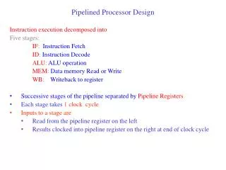
Pipelined Processor Design The operation of the processor are divided into a number of sequential actions, e.g.: 1. Fetch instruction. 2. Fetch operands. 3. Execute operation. 4. Store results or more steps. Each step is performed by a separate unit (stage). Each action is performed by a separate logic unit which are linked together in a “pipeline.”
Pipeline Staging Latches Usually, pipelines designed using latches (registers) between units (stages) to hold the information being transferred from one stage to next. Transfer occurs in synchronism with a clock signal:
Processing time Time to process s instructions using a pipeline with p stages = p + s - 1 cycles
Speedup How much faster using pipeline rather than a single homogeneous unit? Speed-up available in a pipeline can be given by: = Potential maximum speed-up is p, though only be achieved for an infinite stream of tasks (s ) and no hold-ups in the pipeline. An alternative to pipelining - using multiple units each doing the complete task. Units could be designed to operate faster than the pipelined version, but the system would cost much more. Note: This does not take into account the extra time due to the latches in the pipeline version
Dividing Processor Actions • The operation of the processor can be divided into: • Fetch Cycle • Execute Cycle
Fetch/decode/execute pipeline Relevant for complex instruction formats Recognizes instruction - separates operation and operand addresses
Try to have each stage require the same time otherwise pipeline will have to operate at the time of the slowest stage. Usually have more stages to equalize times. Let’s start at four stages: Four-Stage Pipeline OF OS IF EX Space-Time Diagram
Four-stage Pipeline “Instruction-Time Diagram” An alternative diagram: This form of diagram used later to show pipeline dependencies.
Information Transfer in Four-Stage Pipeline Register file Memory Register #’s Contents Latch Latch Latch Instruction Address PC ALU OF IF OS EX Clock
Register-Register Instructions ADD R3, R2, R1 Register file After instruction fetched: Memory Latch Latch Latch Add R3 Instruction PC = PC+4 R2 Address R1 PC ALU OF IF OS EX Clock Note: where R3, R2, and R1 mentioned in the latch, it actually holds just register numbers.
Register-Register Instructions ADD R3, R2, R1 Register file After instruction fetched: Memory Latch Latch Latch Add R3 Instruction R2 Address R1 PC ALU OF IF OS EX Clock Note: where R3, R2, and R1 mentioned in the latch, it actually holds just register numbers.
Register-Register Instructions ADD R3, R2, R1 Register file After operands fetched: Memory Latch Latch Latch Add ----- R3 --- Instruction V2 --- Address V1 --- PC ALU OF IF OS EX Clock V1 is contents of R1, V2 is contents of R2
Register-Register Instructions ADD R3, R2, R1 Register file After execution (addition): Memory Latch Latch Latch ---- --- R3 --- Instruction Add --- Result --- Address V2 --- --- V1 PC ALU OF IF OS EX Clock Note: where R3, R2, and R1 mentioned in the latch, it actually holds just register numbers.
Register-Register Instructions ADD R3, R2, R1 Register file After result stored: R3, result Memory Latch Latch Latch ---- --- -- --- Instruction --- --- --- Address --- --- PC ALU OF IF OS EX Clock Note: where R3, R2, and R1 mentioned in the latch, it actually holds just register numbers.
Register-Constant Instructions (Immediate addressing) ADD R3, R2, 123 Register file Overall: R3, result Memory R2 Latch Latch Latch Add Add R3 R3 R3 Instruction Result V2 R2 Address 123 123 PC ALU OF IF OS EX Clock V2 is contents of R2
Branch Instructions A couple of issues to deal with here: Number of steps needed. Dealing with program counter incrementing after each instruction fetch.
(Complex) Branch Instructions Bcond R1, R2, L1 Offset to L1 held in instruction Overall: Offset If TRUE add offset to PC else do nothing Result (TRUE/FALSE) Register file Memory R2 V1 R1 V2 Latch Latch Latch Bcond Test Bcond V1 R1 Instruction + Result V2 R2 Address Offset Offset Offset PC ALU OF IF OS EX/BR Clock V1 is contents of R1
Simpler Branch Instructions Bcond R1, L1 Tests R1 against zero Overall: Offset If TRUE add offset to PC else do nothing Result (TRUE/FALSE) Register file Memory V1 R1 Latch Latch Latch Bcond Test Bcond V1 R1 Result Instruction + Address Offset Offset Offset PC OF IF OS EX/BR Clock V1 is contents of R1
Dealing with program counter incrementing after each instruction fetch Previous design will need to taking into account that by the time the branch instruction is in the execute unit, the program counter will have been incremented three times. Solutions: Modify the offset value in the instruction (subtract 12). 2. Modify the arithmetic operation to be PC + offset – 12 3. Feed the program counter value through the pipeline. (This is the best way as it takes into account any pipeline length. Done in the P-H book)
Feeding PC value through pipeline BcondR1, L1 Tests R1 against zero Overall: New PC value If TRUE update PC else do nothing Result (TRUE/FALSE) Register file Memory V1 R1 Latch Latch Latch Bcond Test Bcond V1 R1 Result Instruction Address Offset New PC value Offset Add PC PC PC OF IF OS EX/BR Clock V1 is contents of R1
Load and Store Instructions Need at least one extra stage to handle memory accesses. Early RISC processor arrangement was to place memory stage (MEM) between EX and OS as below. Now a five-stage pipeline. LD R1, 100[R2]
ST 100[R2], R1 Note: Convenient to have separate instruction and data memories connecting to processor pipeline - usually separate cache memories, see later.
Number of Pipeline Stages As the number of stages is increased, one would expect the time for each stage to decrease, i.e. the clock period to decrease and the speed to increase. However one must take into account the pipeline latch delay. 5-stage pipeline represents an early RISC design - “underpipelined” Most recent processors have more stages.
Optimum Number of Pipeline Stages* Suppose one homogeneous unit doing everything takes T time units. With p pipeline stages with equally distributed work, each stage takes T/p. Let tL = time for latch to operate. Then: Execution time tex = (p + s - 1) (T/p + tL) Typical results (T = 128, TL=2) In practice, there are a lot more factors involved, see later for some. * Adapted from “Computer Architecture and Implementation” by H. G. Cragon, Cambridge University Press, 2000.