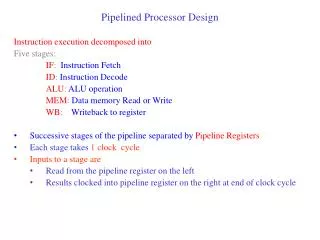
Processor Design
760 likes | 1.39k Views
Processor Design. Computer Architecture CS 215. Registers. Special purpose registers Accumulators (arithmetic registers) Status register. Machine Types. Accumulator machines Limited number of data accumulators 1-address machines Stack machines No register names

Processor Design
E N D
Presentation Transcript
Processor Design Computer ArchitectureCS 215
Registers • Special purpose registers • Accumulators (arithmetic registers) • Status register
Machine Types • Accumulator machines • Limited number of data accumulators • 1-address machines • Stack machines • No register names • Registers organized as a stack • 0-address machine • General register machines • Most often used today • Registers used for almost any purpose
Instruction Sets • Each family of CPUs has its own instruction set • Instruction codes are mapped to instructions • Data movement • Arithmetic • Logic • Control
Instructions • Must contain … • Which operation to perform • Where to find the operand(s), if any • Where to put the result, if any • Where to find the next instruction
Memory Access • Each register has a unique address • Two operations • Read • Write
Memory Access: Read • CPU places an address on the address bus, and a read request on the control bus • Memory unit receives request, decodes address, and locate data at address • Memory unit places data on data bus • Memory unit places a complete message on control bus
Memory Access: Write • CPU places an address on the address bus, value to be written on data bus, and a write request on the control bus • Memory unit receives request, decodes address • Memory unit stores data at address • Memory unit places a complete message on control bus
Immediate i Direct M[i] Indirect M[M[i]] Register direct R[i] Register indirect M[R[i]] Displacement M[R[i]+c]] Relative M[PC+c] Addressing Modes
Load instructions ld, ldr, la, lar Store instructions st, str Arithmetic add, addi, sub, neg Logic and, andi, or, ori, not shr, sha, shl, shc Branching br, brl Miscellaneous nop, stop SRC Instructions
Instruction Formats ld, st, la, addi, andi, ori 31 27 26 22 21 17 16 12 11 4 2 0 Op ra rb c2 ldr, str, lar 31 27 26 22 21 17 16 12 11 4 2 0 Op ra c1
Instruction Formats neg, not 31 27 26 22 21 17 16 12 11 4 2 0 Op ra unused rc unused br 31 27 26 22 21 17 16 12 11 4 2 0 Op unused rb rc (c3) unused Cond
Instruction Formats brl 31 27 26 22 21 17 16 12 11 4 2 0 Op ra rb rc (c3) unused Cond add, sub, and, or 31 27 26 22 21 17 16 12 11 4 2 0 Op ra rb rc unused
Instruction Formats shr, shra, shl, shc 31 27 26 22 21 17 16 12 11 4 2 0 Op ra rb (c2) unused Count 31 27 26 22 21 17 16 12 11 4 2 0 Op ra rb rc (c3) unused 00000 nop, stop 31 27 26 22 21 17 16 12 11 4 2 0 Op unused
Example: cnt: .equ 8 .org 0 seq: .dc 1 next: .dc 1 ans: .dw cnt .org 0x1000 lar r31, loop la r0, cnt la r1, seq loop: ld r2, seq(r1) ld r3, next(r1) add r2, r2, r3 st r2, ans(r1) addi r1, r1, 4 addi r0, r0 -1 brnz r31, r0 stop
CPU Design CPU Control Unit • Control Unit • Generates the control signals in the correct order to effect the correct data path activity • Data Path • Set of interconnections and auxiliary registers • Needed to accomplish overall changes an instruction makes Control signals out Control unit inputs Data Path
Register Transfer Notation • Provides a formal means of describing machine structure and function • Is at the “just right” level for machine descriptions • Does not replace hardware description languages. • Can be used to describe what a machine does (an Abstract RTN) without describing how the machine does it. • Can also be used to describe a particular hardware implementation (A Concrete RTN)
RTN (Cont’d.) • At first you may find this “meta description” confusing, because it is a language that is used to describe a language. • You will find that developing a familiarity with RTN will aid greatly in your understanding of new machine design concepts. • We will describe RTN by using it to describe SRC.
Static Properties • Specifying registers • IR31..0 specifies a register named “IR” having 32 bits numbered 31 to 0 • “Naming” using the := naming operator: • op4..0 := IR31..27 specifies that the 5 msbs of IR be called op, with bits 4..0. • Notice that this does not create a new register, it just generates another name, or “alias” for an already existing register or part of a register.
“if” condition “then” RTN Assignment Operator Dynamic Properties • Conditional expressions: • (op=12) R[ra] R[rb] + R[rc]: ; defines the add instruction This fragment of RTN describes the SRC add instruction. It says, “when the op field of IR = 12, then store in the register specified by the ra field, the result of adding the register specified by the rb field to the register specified by the rc field.”
R[0..31]31..0: Colon separates statements with no ordering Name of registers Register # in square brackets msb # Bit # in angle brackets lsb# .. specifies a range of indices Register Declarations • General register specifications shows some features of the notation • Describes a set of 32 32-bit registers with names R[0] to R[31]
Dummy parameter Naming operator Concatenation operator All bits in register if no bit index given Naming Operator • Defining names with formal parameters is a powerful formatting tool • Used here to define word memory (big endian) M[x]31..0 := Mem[x]#Mem[x+1]#Mem[x+2]#Mem[x+3]:
Memory • Processor State PC<31..0>: • 32-bit register Program Counter IR<31..0>: • 32-bit register Instruction Register Run: • 1-bit run/halt indicator Strt: • Start signal R[0..31]<31..0>: • 32, 32-bit general purpose registers
Main Memory Mem[0..232-1]<7..0>: • 232 addressable bytes of memory M[x]<31..0>: • = Mem[x]#Mem[x+1]#Mem[x+2]#Mem[x+3]:
Instruction Formats op<4..0>: = IR<31..27> • Operation code field ra<4..0>: = IR<26..22> • Target register field rb<4..0>: = IR<21..17> • Operand, address index, or branch target register rc<4..0>: = IR<16..12> • Second operand, conditional test, or shift count register
Instruction Formats c1<21..0>: = IR<21..0> • Long displacement field c2<16..0>: = IR<16..0> • Short displacement or immediate field c3<11..0>: = IR<11..0> • Count or modifier field
Effective Address Calculations • Displacement disp<31..0>:=((rb=0)c2<16..0> {sign extend}: (rb0)R[rb]+c2<16..0> {sign extend, 2’s compliment}): • Relative rel<31..0>:=PC<31..0>+c1<21..0> {sign extend, 2’s comp}:
Instruction Interpretation & Execution instruction_interpretation:=(RunStrt(Run1: instruction_intepretation):Run(IRM[PC]:PCPC+4: instruction_execution): ):
Load & Store Instructions instruction_execution:=(ld(:=op=1)R[ra]M[disp]: load registerldr(:=op=2)R[ra]M[rel]: load register relativest(:=op=3)M[disp]R[ra]: store registerstr(:=op=4)M[rel]R[ra]: store register relativela(:=op=5)R[ra]disp: load displacement addresslar(:=op=6)R[ra]rel: load relative address
Branch Instruction cond:=( c3<2..0>=00: Never c3<2..0>=11: Always c3<2..0>=2R[rc]=0: Register=0 c3<2..0>=3 R[rc]0 : Register0 c3<2..0>=4R[rc]<31>=0: >= 0 c3<2..0>=5R[rc]<31>=1): < 0 br(:=op=8)(condPC R[rb]): Cond branch brl(:=op=9)( R[ra]PC: Branch & link cond(PCR[rb])):
ALU Instructions • Arithmetic Instructions add(:=op=12)R[ra]R[rb]+R[rc]: addi(:=op=13)R[ra]R[rb]+c2<16..0>: sub(:=op=14)R[ra]R[rb]-R[rc]: neg(:=op=15)R[ra]-R[rc]:
ALU Instructions • Logical Operations and(:=op=20)R[ra]R[rb]R[rc]: andi(:=op=21)R[ra]R[rb]c2<16..0>: or(:=op=22)R[ra]R[rb]R[rc]: ori(:=op=23)R[ra]R[rb]c2<16..0>: not(:=op=24)R[ra]R[rc]:
ALU Instructions • Shift Operations n:= ((c3<4..0>=0)R[rc]<4..0>: (c3<4..0>0)c3<4..0>): shr(:=op=26)R[ra]<31..0>(n@0)#R[rb]<31..n>: shra(:=op=27)R[ra]<31..0>(n@R[rb]<31>)#R[rb]<31..n>: shl(:=op=28)R[ra] <31..0>R[rb]<31-n..0>#(n@0): shc(:=op=29)R[ra] <31..0>R[rb]<31-n..0>#R[rb]<31..32-n>
Miscellaneous Instructions nop(:=op=0): No operation stop(:=op=31)run0): Stop instruction instruction_interpretation: End of instr_execution; invoke instr_interpretation
Abstract vs. Concrete RTN • Abstract: What occurs • R[3] R[1] + R[2]; • Concrete: How it occurs • Y R[2]; Z R[1] + Y; R[3] Z; • Control Sequence • R[2]out, Yin; R[1]out, Zin; Zout, R[3]in;
Bus Transfers The Rules of Buses • Only one item can be on the bus during a given clock cycle. • The contents of the bus disappear at the end of the clock cycle. No information is “stored” on the bus from cycle to cycle; any value to be saved must be stored into a register at the end of the clock cycle.
Problems • Pp. 82-83, nos. 2.10, 2.19, 2.23
1-Bus Microarchitecture • Only one value can be placed on the bus at any time
Abstract Vs. Concrete RTN • How would accomplish the following instruction using this architecture? add(:=op=12)R[ra]R[rb]+R[rc]:
Abstract Vs. Concrete RTN add(:=op=12)R[ra]R[rb]+R[rc]: Step RTN
Abstract Vs. Concrete RTN:addi Step RTN T0. MA PC: C PC + 4; T1. MD M[MA]; PC C; T2. IR MD; T3. A R[rb]; T4. C A + c2<16..0> {sign ext.}; T5. R[ra] C;
Abstract Vs. Concrete RTN:ld Step RTN T0-T2 Instruction fetch T3. A (rb=0 0: rb0 R[rb]); T4. C A + (16@IR<16>#IR<15..0>); T5. MA C; T6. MD M[MA]; T7. R[ra] MD;
Abstract Vs. Concrete RTN:st Step RTN T0-T2 Instruction fetch T3. A (rb=0 0: rb0 R[rb]); T4. C A + (16@IR<16>#IR<15..0>); T5. MA C; T6. MD R[ra]; T7. M[MA] MD;
Abstract Vs. Concrete RTN:br Step RTN T0-T2 Instruction fetch T3. CON cond(R[rc]); T4. CON PC R[rb];
Abstract Vs. Concrete RTN:shr Step Concrete RTN T0-T2 Instruction fetch T3. n IR<4..0>; T4. (n=0) (n R[rc]<4..0>; T5. C R[rb]; T6. Shr (:= (n≠0)(C<31..0>0#C<31..1>:n n-1; Shr) ); T7. R[ra] C;
General purpose registers Control signals 5x32 decoder More Detail … ra, rb, rc fields
Try this! • Problem • Extend the SRC instruction set by adding the XOR command (op=19), similar to the AND commandNote: The ALU cannot be altered by adding XOR • Develop both an abstract and concrete RTN for the instruction