Download
1 / 25
260 likes | 463 Views
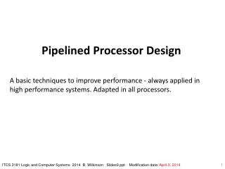
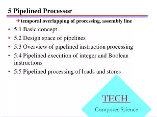
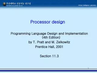
Pipelined Processor Design. Instruction execution decomposed into Five stages: IF : Instruction Fetch ID : Instruction Decode ALU : ALU operation MEM : Data memory Read or Write WB : Writeback to register Successive stages of the pipeline separated by Pipeline Registers

E N D
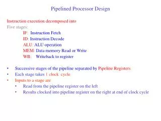
Pipelined Processor Design Instruction execution decomposed into Five stages: IF: Instruction Fetch ID: Instruction Decode ALU: ALU operation MEM: Data memory Read or Write WB: Writeback to register • Successive stages of the pipeline separated by Pipeline Registers • Each stage takes 1 clock cycle • Inputs to a stage are • Read from the pipeline register on the left • Results clocked into pipeline register on the right at end of clock cycle
Execution of lw Instruction: lw Rt, d(Rs) IF ID EX MEM WB P C + 4 PC PC C n t r l C n t r l C n t r l Decode + (rs) REG FILE R e s u l t DATA MEM A L U REG FILE I n s t r u c t i o n D a t a IM (rt) Mux Mux rs rt rt rt rd d EXT
P C P C P C P C P C 5-Stage Processor Pipeline T=1 T=2 T=3 T=4 T=5 IF ID EX MEM WB IF ID EX MEM WB P C P C IF ID EX MEM WB P C P C IF ID EX MEM WB P C P C P C IF ID EX MEM WB
P C P C P C P C 5-Stage Processor Pipeline T=1 T=2 T=3 T=4 T=5 IF ID EX MEM WB P C IF ID EX MEM WB P C P C IF ID EX MEM WB P C P C IF ID EX MEM WB P C P C P C IF ID EX MEM WB
Performance Measures • Instruction Latency Time elapsed between start and finish of the instruction • 5 clock cycles • CPI: Average number of cycles per instruction • n instructions in an ideal p-stage pipeline require n+p-1 cycles • CPI = n+p-1/n = 1 + p-1/n • Isolated instruction (n=1): p cycles • Large n: CPI tends to 1 • IPC : (cycles/instruction) • Number of instructions completed per cycle: 1/CPI : 1/ 1 + (p-1)/n • Tends to 1 instruction/cycle for ideal pipeline • Instruction Throughput (instruction/sec) • Number of instructions completed per second: IPC x Cycles/second = IPC x Clock Frequency
Pipeline Hazards • Hazard • Condition that disrupts the orderly flow of instructions • Requires special attention by hardware and/or software to maintain program correctness and performance • Structural Hazards Contention for hardware resources • Data Hazards Data dependencies between instructions • Control Hazards Disruptions caused by program control flow
Structural Hazards Contention for hardware resources Memory, Register File, ALU Example: Suppose instruction and datamemory were combined A: LD R1, 1000(R2) B: ADD R3, R4, R5 C: ADD R6, R7, R8 D: ADD R9, R10, R11
A F E B C Memory Contention Hazard IF ID EX MEM WB T=1 T=2 T=3 T=4 T=5 T=6 A IF ID EX MEM WB B A IF ID EX MEM WB C D B A IF ID EX MEM WB D C B A IF ID EX MEM WB E D C B IF ID EX MEM WB
A F E B C Memory Contention Hazard IF ID EX MEM WB T=1 T=2 T=3 T=4 T=5 T=6 A IF ID EX MEM WB B A IF ID EX MEM WB C D B A IF ID EX MEM WB D C B A IF ID EX MEM WB E D C B IF ID EX MEM WB
Memory Contention Hazard Time ABCDEF 1 2 3 4 5 6 7 8 9 10 IF ID EX MEM WB IF ID EX MEM WB IF ID EX MEM WB IF ID EX MEM WB IF ID EX MEM WB IF ID EX MEM WB • Instructions A and Dcontend for memory at cycle 4 • Every instruction reads instructions from memory at cycle 1 • LD and SD instructions write to memory at cycle 4 • Solution • Separate instruction and data memories
Structural Hazards • Structural Hazards • Contention for hardware resources • Memory • Is 1 cycle access for memory realistic? • Register File
A F E B C Structural Hazard: Register Contention IF ID EX MEM WB T=1 T=2 T=3 T=4 T=5 T=6 A IF ID EX MEM WB B A IF ID EX MEM WB C D B A IF ID EX MEM WB D C B A IF ID EX MEM WB E D C B IF ID EX MEM WB
A F E B C Structural Hazard: Register Contention IF ID EX MEM WB T=1 T=2 T=3 T=4 T=5 T=6 A IF ID EX MEM WB B A IF ID EX MEM WB C D B A IF ID EX MEM WB D C B A IF ID EX MEM WB E D C B IF ID EX MEM WB
Register Contention Hazard Time ABCDEF 1 2 3 4 5 6 7 8 9 10 IF ID EX MEM WB IF ID EX MEM WB IF ID EX MEM WB IF ID EX MEM WB IF ID EX MEM WB IF ID EX MEM WB • Instructions A and Dcontend for register file at cycle 5 • All instructions (except Store, Branch) write to Register File incycle 5 • All instructions (except jump) read Register File in cycle 2 • Solution: • :Multi-ported register file: Design register file to allow concurrent accesses • 2 Read ports and 1 Write port • Write in first half of cycle, reads in second half • Read returns the value written in first half cycle
Pipeline Hazards • Hazard Condition that disrupts the orderly flow of instructions Requires special attention by hardware and/or software to maintain program correctness and performance • Structural Hazards Contention for hardware resources • Data Hazards Data dependencies between instructions • Control Hazards Disruptions caused by program control flow
Data Dependencies Dependent instructions: access common storage location • I1 and I2 instructions that access a common storage location • Read-after-Read (RAR) dependency • I2 reads the location read by I1 I1: ADD R1, R2, R3 I2 : ADD R4, R5, R2 • Both I1 and I2 read register R2 • Read-after-Write (RAW) dependency • I2 reads the location written by I1 • No instruction between I1 and I2 writes to the same location I1: ADD R1, R2, R3 I2: ADD R4, R1, R2 • I2 reads the value in register R1 that was written by I1
Data Dependencies • I1 and I2 instructions that access a common storage location • Write-after-Read (WAR) dependency: • I2 writes the location read by I1 I1: ADD R1, R2, R3 I2: ADD R2, R4, R5 • I1 must read value of R2 prior to write by I2 • Write-after-Write (WAW) dependency: • I2 writes the location written by I1 I1: ADD R1, R2, R3 I2: ADD R1, R4, R5 • Write of R1 by I1 must not occur after the write by I2 • Final value of R1 due to write by I2 and not I1
A B 1 2 3 4 5 6 IF ID EX MEM WB IF ID EX MEM WB When is a dependency a hazard? WAR Hazard A : ADD R1, R2, R3 B : ADD R2, R4, R5 Register readsoccur at anearlier pipeline stage than write • A reads R2 at cycle 2. • B writes R2 at cycle 6 (or later) • No WAR hazards in this pipelined implementation
A B 1 2 3 4 5 6 IF ID EX MEM WB IF ID EX MEM WB When is a dependency a hazard? WAW Hazard A : ADD R1, R2, R3 B : ADD R1, R4, R5 • Register writes occur only in WB stage • A writes R1 at cycle 5. • B writes R1 at cycle 6 (or later) • No WAW hazards in pipelined implementation
When is a dependency a hazard? RAWHazard A : ADD R1, R2, R3 B : ADD R4, R1, R5 • Hazard possible since register reads occur earlier than writes • A writes R1 at cycle 5 • B may read R1 at cycle 3, 4 or 5 Example: A and B consecutive instructions A B 1 2 3 4 5 6 IF ID EX MEM WB IF ID EX MEM WB • Instruction B reads stale value in R1 beforeit is updated byA (HAZARD!!)
IF ID EX MEM RAW Hazards 1 2 3 4 5 6 7 IF ID EX MEM WB A IF ID EX MEM WB X IF ID EX MEM WB C • A and B separated by 1 instruction: Hazard 1 2 3 4 5 6 7 8 IF ID EX MEM WB A IF ID EX MEM WB X IF ID EX MEM WB Y WB A • A, B separated by 2 instructions • Hazard depends on register file design • No Hazard with split read/write protocol with writes earlier in cycle
1 2 3 4 5 6 7 8 IF ID EX MEM WB A IF ID EX MEM WB X IF ID EX MEM WB Y IF ID EX MEM WB Z RAW Hazards IF ID EX MEM B A, B separated by 3 instructions: No Hazard • Register file design alternatives: • value returned by read equals the value being written at that cycle • value returned by read is the old value • 1 implies no RAW hazard • 2 implies RAWhazard
Pipeline Hazards • Hazard Condition that disrupts the orderly flow of instructions Requires special attention by hardware and/or software to maintain program correctness and performance • Structural Hazards Contention for hardware resources • Data Hazards Data dependencies between instructions • Control Hazards Disruptions caused by program control flow
Lazy Execution of Branch Equal Instruction: beq Rt, Rs, d IF ID EX MEM WB MUX AND P C + 4 PC PC PC C n t r l C n t r l Decode + ADD (rs) REG FILE A L U REG FILE F L A G I n s t r u c t i o n IM (rt) Mux rs rt rd d d EXT <<
Talking Points Additional Discussion points in Lecture: 1. Cache needed for single--cycle access What happens on a miss? Simple calculation to show increase in CPI: 100% instruction cache hits 95% Data cache hit 20% Load/Store instructions Miss Penalty 100 cycles Total stall cycles (per instruction): 20/100 x 5/100 x 100 = 1.0 cycle CPI = 1.0 + 1.0 = 2.0 2. MIPS = 10^6 x CPI x Frequency (Hz) Clock frequency determined by the delay through the pipeline stage faster circuitry less circuitry Deep pipelines with very thin stages: can increase the clock rate at the expense of latency Instruction throughput increases