Download
1 / 61
610 likes | 747 Views
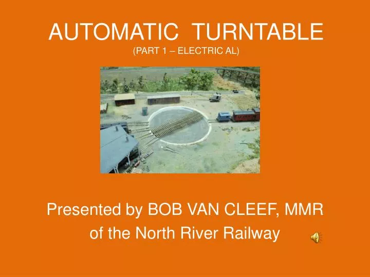
AUTOMATIC TURNTABLE (PART 1 – ELECTRIC AL). Presented by BOB VAN CLEEF, MMR of the North River Railway. This presentation is NOT complete at this time nor will it cover the construction of the actual turntable above table level in more than a general way.

E N D
AUTOMATIC TURNTABLE(PART 1 – ELECTRIC AL) Presented by BOB VAN CLEEF, MMR of the North River Railway
This presentation is NOT complete at this time nor will it cover the construction of the actual turntable above table level in more than a general way. • This optical circuit was first successfully built and proven over 35 years ago. • This clinic shows a modern, updated version with less cost and fewer parts at the expense of slightly more complex circuitry.
A SCRATCH BUILT TABLE Scratch building an optically aligned table is not simple but it does have many advantages. • Stall tracks do not have to be equally spaced. • No switches for stall tracks are required. • No complex mechanical alignment mechanisms that can wear out are used. Alignment is simple and dependable. • No precision parts or carpentry is required. • YES, quite a bit of assembly IS required; This project is NOT for beginners.
FORWARD • The roundhouse and turntable is often the main focus point of a layout yet very few modelers build their own turntable. • There are only a few small simple turntables available on the market today. • Most commercial tables of any reasonable size are expensive, hard to find, have few features and are difficult to use.
THIS CLINIC IS DIVIDED AS FOLLOWS: • Theory of operation • Electronics • PIC device • Support circuitry • Software • Mechanical • Motor • Optics • Overall Construction
THEORY OF OPERATION • This is an optically-based positioning system. • A motor drives the turntable. • A LED projects a beam of light over a pairs of photo cells for each track position. • Circuitry counts the number of cell pairs passed as the table turns and stops all motion when exactly half way between the cell pair of the desired track. • Adjustments are simple and easy. • Accuracy is reliable and close to about +/- .010” • Power to the stall tracks is delivered by a special comutator thus eliminating the need for switches.
A SIMPLE OPTICAL SYSTEM • This is a simulation of an optical turntable system. • A single pair of photo-resisters represent up to 24 pairs or more of cells wired in parallel • The LCD below table level pivots with the bridge of the turntable. • Note that no lens or other optical components are required
HOW IT WORKS Output of cells and motor speed as light source passes. Light directed to either cell will cause a signal for that cell to go from high to low. A low signal from either of (2) cell signals the table is near alignment and slows the motor. A third signal is also generated from one of the cells that has no effect until the other two go low. Then, but only then, when the signal changes, the table stops indexing.
ELECTRICAL CONNECTIONS A slip ring is a method of making an electrical connection through a rotating assembly. This complex slip ring is made from a printed circuit board. motor brushes on the underside of a drive wheel route power to the light source and various tracks around the table. (More on this later)
THE ELECTRONICS A single PIC device contains most of the circuitry required for this project. Special chips are used to control the motor and to display the status of turntable operation. A small number of discrete components complete the project. A USB interface is used to program the PIC only during the development of the system.
THE PIC MICRO CONTROLER • 16-bit architecture • 16K x 14bit Program Memory • 1024 x 8 bit RAM • Clock, timing and all support circuitry • Serial Programming I/F • About 56 other components all in a single 64-pin package slightly larger than a thumbnail for just $4
A TOOLKIT IN A BOX In addition to the RAM ROM it contains: • 6-1/2 ports • A/D converters • Timers • UARTS • LCD AND LCD DRIVERS • COMPARATORS • SEVERAL OTHER FUNCTIONS
PINS HAVE MULTIPLE USES • Most pins have multiple uses • Device must be configured to define pin use • Configuration can be changed in mid-program
CONFIGURING THE PIC DEVICE This project makes use of the (3) comparators contained within this device. • Note the multiplexed inputs. • The polarity of the output can be inverted or accessed without the use of an external pin. • This leaves the unused pins free for other uses.
PROGRAMMING THE PIC PIC devices are designed to be programmed without being removed from their socket. A USB port powers the programmer as well as the data to be programmed. The programmer supplies all voltages and signals required to program the PIC device.
JUMPERS Four jumpers provide direct access to up to 15 test routines as well as the normal “RUN” mode. This simplifies testing This also allows multiplexing of multiple tables on one system.
CONTROL PANEL Three buttons control the table. CW CCW RESET The 8-character LCD displays The number of button presses Direction of rotation Status Rapid travel Seeking (slow travel) Stop (in Position) Ready
LCD DISPLAY A simple, inexpensive LCD display is used to show the turntable status. I shows (1) line of (8) characters. Only (8) wires are required to connect the display
MOTOR CONNECTIONS A driver uses circuitry similar to a DCC decoder to drive the motor No decoder is required. It can be configured to run using a wide range of voltages. Logic circuits are electrically independent of motor power. A simple 2-speed circuit controls the motor. Note the extra circuit to turn the light source on and off.
TURNTABLE CONTROLER • Very few support components are required using a PIC device.
5 and 8 volt POWER SUPPLY A simple power supply • The turntable runs from a 16v DC wall transformer. • Two common voltage regulators provide the required voltages
Micro Engineering U2 Programmer • USB interface for easy use with virtually all computers • Generates all required voltages required for programming. • Works with entire range of PIC devices with proper interfaces • Firmware can be automatically updated via host computer as new PIC devices become available.
CCS “C” Compiler and IDE EVERYTHING YOU NEED TO GET STARTED • Custom Computer Services (CCS) offers a complete range of software for PIC devices. • One product offers a full implementation of the “C” and other languages at a very low price. • It is easy to install. • All components work well together.
PRINTED CIRCUIT SLIP RING • This printed circuit board (PCB) provides connections to the rotating bridge. • The Center and first band provide power to the “light gun” • The next band simply provides clearance for power feeds • The next band provides power to one of the bridge rails. Note the split to allow proper reversing. • The outer band energizes one, but only one stall track at a time.
RESOURCES Digikey http://www.digikey.com/ Source for wide variety of electronic related parts and hardware including LEDs, Wire, Solder, Copper wire, printed circuit board and headers. MicroMark http://www.micromark.com/ Source for small tools and materials useful for modeling. Custom Computer Services (CCS) http://www.ccsinfo.com “C” and several other higher level languages for PIC devices Microchip http://www.microchip.com Manufacturer of PIC devices and several programming accessories Proto-Advantage - http://www.proto-advantage.com Custom design and assembly of SMT devices and related materials.
THE END This presentation has been brought to you by the North River Railway Bob Van Cleef 46 Broadway Coventry, CT 06238 http://www.northriverrailway.net
AUTOMATING A TURNTABLE(PART 2) Presented by BOB VAN CLEEF, MMR of the North River Railway
MOTORS • Vex Robotics carries a line of motors, gears and metal channels designed for building robots. • These are perfect for building a rugged mechanism the runs at whatever speed desired. • Parts include gears, chains, tank tracks almost any drive desired including belts.
BRUSHES ON DRIVE DISK • Brushes for motors are used to collect power from the comutator • The are attached to thin metal springs to allow maximum movement
PHOTO CELLS ON TABLE BASE Photo cells are mounted on a pylon using a single screw Fine positioning can be accomplished by simply turning the pylon slightly until proper alignment is achieved. Simple and crude? Yes, but very effective and dependable.
DRIVE MOTOR • Any small inexpensive motor can be used to drive a turntable • This system used a simple rubber shaft to turn the disk • The clutch drive was required to prevent any binding at slow speeds.
IMPROVED DRIVE SYSTEM • A future drive will be a bit more complex • The motor will be mounted solidly and a spring-loaded pulley will keep a more reliable tension on the drive disk. Drive belt made from heat-shrink tubing used to turn drive disk
GENERIC CONSTRUCTION NOT TO SCALE
A BRIEF HISTORY Turntables were rare in the first early model railroad layouts. The First crude table mentioned in the July ‘42 MR used a phonograph table as the base and was manually aligned. In August of the same year a much more advanced “automatic” table featured both power to the stall tracks and a mechanical positioning system. Systems in this era used a split ring rail to power the bridge track. Several articles in the MR and other magazines have appeared since then with many differences in the construction to the bridge and pit portions of a turntable (see Sept 57, Aug and Sept ‘63 and March ’72 but few advances were made in the drive mechanism. The exception was a photo-cell system described in the Nov ’66 MR using a single photo-cell and lens. In Oct ‘58 Atlas produced a small, inexpensive self indexing table that became quite popular in both motorized and manual versions. Since then most commercial tables have been very expensive, not automatically aligned and required switches to apply power to the stall tracks.
AN “IMPROVED” TABLE Unsatisfied with what was available at the time, I built a turntable with several novel features. Because the North River already used a computer controlled block system it only seemed logical to use a computer to control the turntables too. At the time I worked with numeric controlled machines with optical positioning systems and found that with a few modifications the principal worked extremely well. Positioning was based on a beam of light, not falling on one photo cell, but falling exactly half-way between pairs of photocells. It also turned out that by using a printed circuit board under the table eliminated the need for switches for the stall tracks as well as eliminating the need for pulling power from a split ring rail to power the bridge track. This system worked well for over 35 years with only two problems. Controlling the motor for the final track alignment required the dedicated attention of the computer at the expense of all other functions of the computer until the alignment was complete. Also, The rubber drive wheel has dried out and decayed causing unreliable operation.
A NEW, “IMPROVED” TABLE The North River Railway has recently been going through a complete renovation to improve and expand the control system, the turntables included. The new system will contain turntables with a more detailed superstructure and will operate independently of the main computer with a dedicated controller of their own. A modern PIC device greatly simplifies the circuitry involved without interrupting operation on the rest of the layout while hardware designed for robots will hopefully provide more reliable operation.
GENERIC BRIDGE CONTRUCTION • Very little variations in general construction. • All had some sort of central pivot, the bridge proper, a deck, and usually some sort of end support. • Dimensions varied to size and weight of locomotives
DECK PLAN FOR BRIDGE • Ties are laid on top of the bridge, some or all of which extend the entire width of the deck. • The deck covers pretty much the entire bridge as it must carry a lot of foot traffic around the locomotive.
BRIDGE SUPPORT • Use a truck to support the bridge. • A narrow gauge truck can be used here with smaller wheels • Remove wheels from one side of truck • Mount truck in usual way so it can pivot and follow the ring rail • “Hide” the truck behind the bridge sides