Download

1 / 13
190 likes | 1.31k Views
AUTOMATIC DUSK TO DAWN (EVENING ON TO MORNING OFF). Introduction. This project is based on LDR for automatic lights flicker due to the change in light intensity at dawn and dusk . The circuit described here can solve the problem and switch ON the

E N D
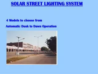
AUTOMATIC DUSK TO DAWN (EVENING ON TO MORNING OFF)
Introduction This project is based on LDR for automatic lights flicker due to the change in light intensity at dawn and dusk. The circuit described here can solve the problem and switch ON the lamp instantly when the light intensity decreases below a preset level. The voltage across LDR depends on the light intensity. In day light, LDR has low resistance and the input voltage to the threshold comparator goes above and its output becomes zero, which resets the internal flip-flop of IC. At sunset, the resistance of LDR increases, and the voltage at the input of the threshold comparator decreases below and that of the trigger comparator goes below.
EMBEDDED SYSTEMS Definition for :- EMBEDDED SYSTEMS • A combination of hardware and software which together form a component of a larger machine. • An example of an embedded system is a microprocessor that controls an automobile engine. • An embedded system is designed to run on its own without human intervention, and may be required to respond to events in real time.
LDR A photoresistor or light dependent resistor (LDR) is a resistor whose resistance decreases with increasing incident light intensity. It can also be referred to as a photoconductor. A photoresistor is made of a high resistance semiconductor. If light falling on the device is of high enough frequency, photons absorbed by the semiconductor give bound electrons enough energy to jump into the conduction band.
555 TIMER • The 555 Timer IC is an integrated circuit (chip) implementing a variety of timer and multivibrator applications. • The original name was the SE555 (metal can)/NE555 (plastic DIP) and the part was described as "The IC Time Machine". • Depending on the manufacturer, the standard 555 package includes over 20 transistors, 2 diodes and 15 resistorson a silicon chip installed in an 8-pin mini dual-in-line package (DIP-8)
IR LED An IR LED, also known as IR transmitter, is a special purpose LED that transmits infrared rays in the range of 760 nm wavelength. Such LEDs are usually made of gallium arsenide or aluminum gallium arsenide. They, along with IR receivers, are commonly used as sensors. The appearance is same as a common LED. Since the human eye cannot see the infrared radiations, it is not possible for a person to identify whether the IR LED is working or not, unlike a common LED. To overcome this problem, the camera on a cell phone can be used. The camera can show us the IR rays being emanated from the IR LED in a circuit.
555 TIMER The 555 Timer IC is an integratedcircuit (chip) implementing a variety of timer and multivibrator applications • The 555 has three operating modes: • Monostable mode: in this mode, the 555 functions as a "one-shot". Applications include timers, missing pulse detection, switches, touch switches, frequency divider, capacitance measurement, pulse-width modulation (PWM) etc. • Astable - free running mode: the 555 can operate as an oscillator. Uses include LED and lamp flashers, pulse generation, logic clocks, tone generation, security alarms, pulse position modulation, etc. • Bistable mode or Schmitt trigger: the 555 can operate as a flip-flop, if the DIS pin is not connected and no capacitor is used. Uses include bounce free latched switches, etc.
The resistor, RS is connected in series with the zener diode to limit the current flow through the diode with the voltage source, VS being connected across the combination. The stabilised output voltage Vout is taken from across the zener diode. The zener diode is connected with its cathode terminal connected to the positive rail of the DC supply so it is reverse biased and will be operating in its breakdown condition.