Download
1 / 21
220 likes | 984 Views
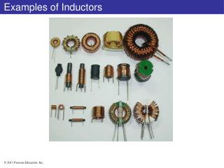
Foil Windings in Power Inductors: Methods of Reducing AC Resistance. Weyman Lundquist President and CEO West Coast Magnetics. SMPS Inductor Winding Resistance Includes AC and DC Resistance. Every successful design requires minimization of total AC plus DC winding losses.

E N D
Foil Windings in Power Inductors:Methods of Reducing AC Resistance Weyman Lundquist President and CEO West Coast Magnetics
SMPS Inductor Winding Resistance Includes AC and DC Resistance Every successful design requires minimization of total AC plus DC winding losses.
Comparison of DC Resistance:Foil, Solid Wire & Litz Wire FOIL SOLID WIRE 50/40 awg LITZ WIRE DCR = 1.9mΩ DCR = 4.3 mΩ DCR = 22.9mΩ • Foil windings: • Fast and easy to wind • Do not require bobbins or other supports
Components of Winding Losses Resistive loss Eddy-current loss dc loss ac loss “ac resistance” Source: J. Pollock Thayer School of Engineering at Dartmouth
Skin Effect B-Field InducedCurrent x MainCurrent J Current Density • Skin Effect • An isolated conductor carrying high-frequency current which generates a field in itself that forces the current to flow near the surface of the conductor.
oo xx ooo xxx ooo xxx ooo xxx xx oo Proximity Effect B-Field InducedCurrent J MainCurrent Current Density x • Proximity Effect • An isolated conductor is placed in an uniform external field • External field results from other wires and windings near the conductor but mainly from the field present in the core window.
Magnetic Field Inside Core Window Ungapped E-core Gapped E-core
Magnetic Field Inside Gapped Inductor Core Window Legend: Red: strong field Blue: weak field Lines: constant field magnitude Gapped E-core
Current Distribution:Ungapped E-Core and Gapped E-Core Full Foil: Ungapped Core Shaped Foil: Gapped Core AC current evenly distributed on surface of foil across full width of foil. AC current pulled to small copper cross section in the vicinity of the gap. Shaped Foil is a patented technology developed by Professor Charles Sullivan and Dr. Jennifer Pollock at Dartmouth College.
Patented Inductor Technology • Very Low DCR, High Window Utilization • Foil winding • Low AC Resistance • AC loss reduction comparable to litz wire • SIGNIFICANTLY LOWER TOTAL WINDING LOSSES Shaped Foil is a patented technology developed by Professor Charles Sullivan and Jennifer Pollock at Dartmouth College.
Experiment: Is the New Technology Really Better? • Objective: A conclusive comparison of the new technology to conventional windings • Step 1: Define the Inductor • Inductance: 90 uH • Current: 40 Adc • Ripple: Triangle wave at 50 kHz • Core: E70/33/32 Epcos N67 material • Gap: 2.64 mm (1.32 mm each center leg) • Turns: 15
Experiment: Is the New Technology Really Better? • Step 2: Wind inductors with conventional windings using best practices • Full window • Single layer • Step 3: Determine winding losses for each inductor as a function of ripple magnitude
400/40 Litz 20/32 Litz Solid Wire Long Cut Prototype Cut Full Foil 20/32 Litz Solid Wire 50/40 Litz Winding Cross Sections
Method of Estimating Losses • DC Resistance • Measure voltage drop under 5 Amp DC load • Core Losses • Derived from Epcos loss curves • AC resistance • Sweep from 10 kHz to 200 kHz with Agilent 4294A network analyzer • Use Fourier decomposition to translate sinusoidal sweep data to triangular waveform
Total Loss Comparison:50 kHz Solid Wire 40 awg litz Full Foil 32 awg litz Shaped Foil Tech. Shaped Foil Tech.
Total Loss Comparison:200 kHz Full Foil Solid Wire 40awg litz Shaped Foil Tech. Shaped Foil Tech. Shaped Foil Tech. Shaped Foil Tech. Shaped Foil Tech.
Experimental Verification Source: J. Pollock Thayer School of Engineering at Dartmouth 1.4 Inductance = 97 μH Number of turns, N = 15 Core size: E71/33/32 Ripple ratio = 20% 1.2 Full-width Foil 1 0.8 Rac, Ω Prototype Notched Foil #3 0.6 Prototype Notched Foil #2 Prototype Notched Foil #1 0.4 Optimization Program Loss 0.2 FEA of Notched Foil 0 0 50 100 150 200 250 Frequency, kHz
Additional Development Work Completed: • Optimization of Foil Shape (cutout) for minimum loss. • Simulation program to predict copper losses in foil windings for full foil and shaped foil windings. • Simulation program to plot inductance vs. Idc for gapped cores. • Optimization of foil shape in distributed gap (powdered cores).
Foil Shape Optimization in Distributed Gap, Powdered Cores Source: Jennifer Pollock. Optimizing Winding Designs for High Frequency Magnetic Components. PHD thesis, 2008
Weyman Lundquist, President West Coast Magnetics 4848 Frontier Way, Ste 100 Stockton, CA 95215 www.wcmagnetics.com 800-628-1123 Thank you for your time The author gratefully acknowledges Professor Charles Sullivan, Thayer School of Engineering at Dartmouth and Jennifer Pollock, PHD EE for their work and contributions to this presentation.