Download
1 / 28
320 likes | 656 Views
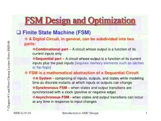
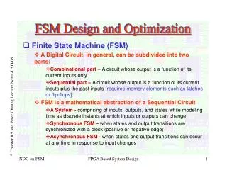
Design and Development of the FSM (Fast steering Secondary Mirror). Myung Cho, NOAO-GSMTPO Kwijong Park, KASI Young- Soo Kim, KASI. OUTLINE. Prior Work: Magellan Secondary Mirror modeling FSM Configuration 3. Design and Development (work in progress) 4. GMT FSM Performance Predictions

E N D
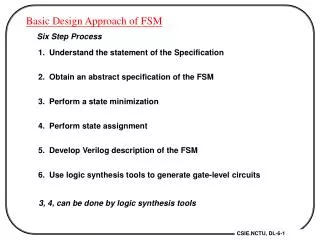
Design and Development of the FSM (Fast steering Secondary Mirror) Myung Cho, NOAO-GSMTPO Kwijong Park, KASI Young-Soo Kim, KASI October 4, 2010 GMT2010: Design and Development of FSM
OUTLINE • Prior Work: Magellan Secondary Mirror modeling • FSM Configuration • 3. Design and Development (work in progress) • 4. GMT FSM Performance Predictions • a. Gravity Analysis • b. Thermal Analysis • c. Natural Frequency analysis • d. Lateral support flexure analysis • e. Sensitivity analysis • f. Zenith Angle effects • 5. Summary and Conclusion • 6. Next Steps October 4, 2010 GMT2010: Design and Development of FSM
Magellan Heritage Magellan heritage: Magellan secondary mirror GMT Primary: 25.4m (8.4m x 7) Secondary: 3.2m (1.06m x 7) Shape: Ellipsoid Focal ratio: F/0.7 Final focal ratio: F/8 Magellan telescope Primary: 6.5m Secondary: 1.3m Shape: Paraboloid Focal ratio: F/1.25 Final focal ratio: F/11.0 ※ Gregorian 6.5m Magellan telescope 25.4m GMT October 4, 2010 GMT2010: Design and Development of FSM
Magellan M2 Assembly Secondary Mirror Assembly of Magellan telescope For GMT FSM design and development, take a conservative engineering approach; utilize concepts established from the F/11 M2 of Magellan telescope. October 4, 2010 GMT2010: Design and Development of FSM
GMT and GMT FSM Primary: 25.4m (8.4m x 7) Secondary: 3.2m (1.06m x 7) Shape: Ellipsoid Focal ratio: F/0.7 Final focal ratio: F/8 Gregorian GMT F/8 Gregorian beams Conjugated M1 and M2 October 4, 2010 GMT2010: Design and Development of FSM
FSM assembly layout October 4, 2010 GMT2010: Design and Development of FSM
FSM optical prescription • FSM optical prescription (as of 9/2010): • FSM M2 nominal segment Configuration: 1060mm 175mm 140mm October 4, 2010 GMT2010: Design and Development of FSM
FSM Error Budget specification Error budget: Encircled Energy diameters at 80% (EE80) Orientation80% EE Specifications Zenith 0.020” (arc-seconds) Horizon 0.030” Figure error 0.039” October 4, 2010 GMT2010: Design and Development of FSM
Assumptions in FE • Finite Element mirror model • 3D solid elements • Center mirror of the FSM array (on-axis) • Clear aperture in the optical surface evaluations: OD=1060mm • Solid Zerodur concave lightweight (63%) • Nominal mirror thickness: 140mm • RADCV=4.2m; sag=0.031m • Center of gravity (CG) = 0.0205m (from vertex) • Mass=105 kg; Ixx=6.3 kg-m2, Izz=12.3 kg-m2 at CG • CTE = 20 E-9 /’C • Support systems • Axial support = 3 point mount with vacuum • Lateral support = single central flexure Y X FSM local coordinates October 4, 2010 GMT2010: Design and Development of FSM
FSM Support system • Three axial support (defining points) mounted at the mirror back surface • Axial supports oriented parallel to the optical axis (vertical, Z-axis) • Axial gravity is fully compensated by a vacuum system at Zenith • Lateral gravity is held by a flexure at the mirror center position on the M2 CG plane. FSM support system October 4, 2010 GMT2010: Design and Development of FSM
Support system – FE modeling • Axial support: Vacuum floating system • Atmospheric pressure was applied on the entire front surface of the FSM from the vacuum • Magnitude of the atmospheric pressure is • equivalent to the axial gravity of FSM • Reaction force at the three axial supports is to be zero; therefore, the FSM is floating • This floating axial system provides a low surface error in Zenith. • Lateral support: Flexure system • FSM gravity is held by a flexure at the mirror • center location • Line of action is on the mirror CG plane • No axial force is to be induced at Horizon W: Weight P: Atmosphere pressure (counter-pressure) October 4, 2010 GMT2010: Design and Development of FSM
Mirror Blank Optimization Four different configurations (depth effect): 1. Gravity print-through 2. Natural Frequency A. 100mm : 78.8kg Baseline: favorable configuration for stiffness and stress requirements B. 120mm : 84.1kg Depth=140mm Face sheet thickness=20mm Mass=105kg C. 140mm : 89.3kg D. 150mm : 91.9kg E. 150mm (rib = 10mm) : 118.4kg October 4, 2010 GMT2010: Design and Development of FSM
FSM: Gravity Print-through Axial Gravity (Gz+vacuum) Lateral Gravity (Gy) RAW (un-corrected)) P.T.T corrected PTT: RMS=6.1 nm surface PTT: RMS=3.8 nm surface Optical Surface deformation maps October 4, 2010 GMT2010: Design and Development of FSM
FSM: thermal gradient, T(z) Thermal gradients delta T =1oC/0.1m along Z axis (Optical axis) (CTE = 20 x 10-9 /oC) P.T.T corrected PV=22nm; RMS=6.3nm surface Displacement in Z: Max.= 18 nm; PV=35 nm Mechanical and Optical surface deformations October 4, 2010 GMT2010: Design and Development of FSM
Natural Frequency (first mode) 1st Mode Shape: Astigmatism at 720 Hz 1st natural frequency mode with free-free condition Mirror mass = 105 Kg in the FE model October 4, 2010 GMT2010: Design and Development of FSM
Natural mirror mode (low order modes) 1 3 4 6 8 10 12 14 16 17 19 21 October 4, 2010 GMT2010: Design and Development of FSM
Typical Lateral Flexures in trade Thickness of Disk Flexure 8.68mm 5mm 0.7mm 15mm 10.16mm 100mm Sample: Section Plane of Lateral Flexure October 4, 2010 GMT2010: Design and Development of FSM
Lateral Flexure Trade study Stress analysis of lateral flexure was performed initially based on thickness and materials provided by GMTO. Further assumptions were made for parametric study. This work is in progress. Typical results during trade study in static, buckling and non-linear analysis y x Buckling analysis Stress calculation Lateral deformation October 4, 2010 GMT2010: Design and Development of FSM
Sensitivity: Axial gravity/vacuum Axial gravity compensated by pressure Gravity 97% compensation Fully Balanced 3% residual by axial support 10N each Atmosphere pressure RMS=4.1nm surface 3% residual force by lateral support (work in progress) RMS=3.8nm surface Optical Surface deformation maps October 4, 2010 GMT2010: Design and Development of FSM
Sensitivity: vacuum seal Seal force applied along the edge of front surface (Flange) (currently assumed a uniform distribution) 10 N/m along radial direction 10 N/m along optical axis RMS=1.0nm surface RMS=12.2nm surface Focus corrected RMS=3.9nm RMS=0.4nm October 4, 2010 GMT2010: Design and Development of FSM
Zenith Angle Dependence Gravity Print-through effects from Zenith angle variations • Print-through from Zenith variation • Combination of optical surfaces from Axial and Lateral cases • Axial support print-through • RMS surface 3.8 nm • Lateral support print-through • RMS surface 6.1 nm • RMS calculations based on surface polished out at FSM face-up October 4, 2010 GMT2010: Design and Development of FSM
Optical calculations (AXIAL) Surface error Slope X Slope Y EE80 diameter October 4, 2010 GMT2010: Design and Development of FSM
Optical calculations (LATERAL) Surface error Slope X Slope Y October 4, 2010 GMT2010: Design and Development of FSM
Optical calculations (ZA=60o)(polished and tested at FSM face-up) Surface error Slope X Slope Y October 4, 2010 GMT2010: Design and Development of FSM
Structure Function calculations (ZA=60o) Structure function of random variable, P(r) D() = < | P(r+ ) - P(r) |2 > Phase map RMS WFE: 11.2 nm Structure function at ZA=60o: sqrt(D) in WFE October 4, 2010 GMT2010: Design and Development of FSM
Summary and Conclusion • FSM mirror blank optimum configuration: • D=1.06m; depth=140mm; face plate thickness=20mm; mass=105kg • Lightweight glass or glass ceramic mirror • FSM support system provides adequate optical performances: • Gravity print-through effects: – met error budget • Axial gravity: 3.8nm RMS surface; EE80 = 0.007 arcsec (< 0.020) • Lateral gravity: 6.1nm RMS surface; EE80 = 0.005 arcsec (< 0.020) • FSM thermal effects were accessed: • Thermal soak, thermal gradients • Natural frequency analysis for FSM mirror blank: • Lowest mode is at 720 hz (astigmatic mode) – stiff mirror • Optical performances at various Zenith angles:– met error budget • Assume: FSM figured and tested at its face up position • At ZA=60 degrees: EE80 = 0.005 arcsec (< 0.039) October 4, 2010 GMT2010: Design and Development of FSM
Next Step • FSM performance evaluations • Support sensitivity • Vacuum seals and seal force sensitivity • FSM mirror support system trade study • Axial support : • Vacuum support • Lateral support : • Lateral support diaphragm/flexure • Stiffness of axial and lateral supports • Work with GMTO for Magellan Secondary mirror engineering document: • Lateral support flexure and bonding procedure • Vacuum October 4, 2010 GMT2010: Design and Development of FSM
Acknowledgments The authors gratefully acknowledge the support of the GMT Office, Matt Johns and Stephen Shectman. This work was partially contributed by the scientists and engineers from the KASI and KRISS of Korea. Students of the University of Arizona are also greatly acknowledged. The individual contributors are: Il Kweon Moon, Andrew Corredor, Christoph Dribusch, Ju-Heon Koh, Eun-Kyung Kim. October 4, 2010 GMT2010: Design and Development of FSM