Download
1 / 1
10 likes | 243 Views
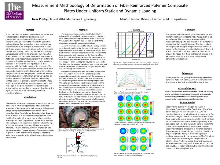
Shock tube. Shock wave. Pressure . transducer. W. s. Steel plate. ?. Primary . Primary . Mirror A. Mirror B. Secondary mirror A . Secondary mirror B . Triggering signal. Phantom . High speed . camera. Methods.

E N D
Shock tube Shock wave Pressure transducer W s Steel plate ? Primary Primary Mirror A Mirror B Secondary • mirror A Secondary • mirror B Triggering signal Phantom High speed camera Methods Fiber reinforced polymer composite materials are rising in popularity in structural applications. Their combined properties of light weight and high strength, stiffness, and energy absorption make them ideal for use air and ground vehicles. The challenge that arises when designing these materials is to maximize certain properties, or to combine the materials in a way that produces a desired property for a specific application. The variables involved with this type of heterogeneous material include the type of polymer or matrix, the types of fibers, matrix-fiber interface, laminate interface, laminate orientation, and lay-up sequencing. The examination of these properties in response to static and dynamics loadings is needed to understand composite material performance in structural applications. Abstract Introduction The large scale high resolution shock tube in the City College of New York’s facility was used to produce both the static and dynamic loadings on the test plates. A pressure transducer installed a short distance from the end of the shock tube measured the pressure in the tube. A laser micrometer was used for all static loading test and some dynamic loading tests. For some static loading tests the laser micrometer was attached to a sliding mechanism with a built-in infrared position sensor to record the position of the laser micrometer as it moved across the diameter of the plate. The static loading was produced by connecting an air compression system to the shock tube. Pressure in the tube was measured on an analog pressure gage during the tests. The data from the pressure transducer, laser micrometer, and infrared sensor were all recorded by a single computer with custom data acquisition software. The dynamic loading tests were performed using a shock wave produced by the shock tube. Shockwaves were produced in the shock tube by sealing off the high pressure chamber at the end of the shock tube with an aluminum diaphragm designed to fail in a certain range of pressures. The high pressure chamber was then pressurized until the diaphragm failed, causing a shockwave to travel down the shock tube and into the test plate installed in the end cap. The deformation of the plate as a result of the dynamic loading from the shockwave was measured using time-resolved catadioptric stereo digital image correlation or TRC-SDIC, that allowed for measurement of both in-plane out-of-plane deformations. This method consists of a high-speed camera and a system of mirror to produce stereo images of the test plates for the camera to record. Measurement Methodology of Deformation of Fiber Reinforced Polymer Composite Plates Under Uniform Static and Dynamic Loading Isaac Pinsky, Class of 2014, Mechanical Engineering Mentor: Feridun Delale, Chairman of M.E. Department Isaac Pinsky is a senior working on his degree in Mechanical Engineering at The City College of New York. Before he began his academic career at CCNY he completed two years in a Jewish seminary program at The Rabbinical College of America in Morristown, New Jersey. Once he gained a secure foundation in his Jewish heritage he focused on a career in mechanical engineering. After completing his bachelor’s degree, he plans to work in the power generation industry as a mechanical engineer. Isaac Pinsky chose to do research in materials science to further expand his knowledge and experience in different engineering fields. He began work with a group of graduate students under the mentorship of Prof. Delale to study the properties of fiberglass composites with additives. Isaac Pinsky has strong ties with the American Society of Mechanical Engineers Student Section at CCNY, and served as secretary and executive board member for the section during his junior year. Results Student Profile References The two methods of measuring the deformation of fiber reinforced polymer composite plates have proven to be very effective. The laser micrometer and sliding mechanism allow plastic deformation of the plates to be displayed easily in graphical format. The time resolved catadioptric stereo digital image correlation method is a robust method capable providing displacement data in X, Y, and Z directions, but X and Y direction could not be shown. It is hoped that these methods will be used in the experimental testing of fiber reinforced polymer composites with additives. Summary Jahnke, D. (2013). The Effect of Shockwave Impingement on Composite Plates with Nano Additives. New York, New York: City College of New York, Mechanical Engineering Dep. Due to the many parameters involved in the manufacture and composition of composite materials, their characteristic properties are difficult to analyze and extensive testing is required to obtain both qualitative and quantitative data. A standard testing methodology was developed to measure plastic deformation in fiber reinforced polymer composite plates under uniform static and dynamic loadings. Both static and dynamic loadings were produced using CCNY’s large-scale high-resolution shock tube facility. The plastic deformations produced in static tests were measured using a laser micrometer with a custom-built sliding mechanism. A pressure transducer was used to measure the loadings that were then correlated with the displacement of the test plates. The plastic deformations produced in the dynamic tests were measured using time-resolved catadioptric stereo digital image correlation with a high speed camera and a simple mirror setup. Steel and aluminum plates were tested for use as a baseline comparison. The static load testing method resulted in consistent experimental data. These results altered slightly from plate theory due to a lack of zero-slope at the plate boundary. The dynamic load testing method also resulted in consistent data, but with a slight variations from the inherent symmetry of experimental setup. Figure 3: These displacement results of the pressure cycling of a composite plate were produced by aiming the micrometer at the center of the plate. Acknowledgments I would like to thank Professor Feridun Delale for allowing me to participate in this research project, and graduate student Doug Jahnke for all he has taught me about experimental research in composite materials. Figure 4: Results of a pressure cycling recorded using the laser micrometer on its sliding mechanism. Figure 5: Results of a dynamic loading test on an aluminum plate recorded using TRC-SDIC (Interval of 0.13 ms) Figure 1: The working end of the shock tube with the laser micrometer in place. The black markings on the plate are used for TRC-SDIC Figure 6: Results of a dynamic loading test on a composite plate recorded using TRC-SDIC (Interval of 0.13 ms) Figure 2: The experimental setup for a dynamic loading test using TRC-SDIC