Download
1 / 10
110 likes | 262 Views
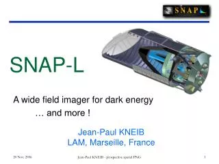
SNAP ACS Requirements. Henry Heetderks Space Sciences Laboratory, UCB. The SNAP Observatory. Secondary Mirror Hexapod Bonnet. Door Assembly. Main Baffle Assembly. Secondary Metering structure. Solar Array, ‘Sun side’. Primary Mirror. Optical Bench. Solar Array, ‘Dark side’.

E N D
SNAP ACS Requirements Henry Heetderks Space Sciences Laboratory, UCB
The SNAP Observatory Secondary Mirror Hexapod Bonnet Door Assembly Main Baffle Assembly Secondary Metering structure Solar Array, ‘Sun side’ Primary Mirror Optical Bench Solar Array, ‘Dark side’ Instrument Metering Structure Instrument Radiator Tertiary Mirror Instrument Bay CCD detectorsNIR detectorsSpectrographFocal Plane guiders Cryo/Particle shield Fold-Flat Mirror Spacecraft ACS CD & H Comm Power Data Solid-state recorders Shutter Hi Gain Antenna H. Heetderks
Observatory Exploded View showing S/C To the extent possible “Spacecraft” components (including the ACS) will be mounted on the Spacecraft portion of the Observatory. Critical items such as the Star Trackers and the IRU’s will be mounted on the optics bench. Optics Bench with Focal Plane Spacecraft Portion of Observatory H. Heetderks
Observatory Mass and Structural Properties • Observatory mass: • Current estimate is 1625 kg • Maximum capability of Delta IV to SNAP orbit is 2020 kg • C.G. is 1.6 meters above the separation plane • Center of (solar) Pressure is approximately 3.3 meters above the separation plane • Cross Sectional area is approximately 2.8 x 6.7 meter^2 • The principal axis MoIs are: Ixx = 3200 kg-m2 (Sun pointing direction) Iyy = 3400 kg-m2 Izz = 1200 kg-m2 (Optical axis) • Structural modal frequencies will meet Delta IV requirements • 27 Hertz Axial • 10 Hertz Lateral H. Heetderks
Requirements on the SNAP ACS System Operation of the ACS system will typically consist in keeping the telescope pointed at a fixed target for a period of time and then moving to a new target. 1) For large changes of pointing direction (i.e. of any size), we require the ability to drop the target into 3x3 Arcsec box with a 98% confidence . • Change of the telescope pointing direction will be done with the science instrument shutter closed. 2) The time allowed to make the pointing direction change of item 1) is a function of the step size: Step Size Settling Time 3 Arcminutes 30 Seconds 1 Degree 2 Minutes 15 Degrees 6 Minutes 180 Degrees 60 Minutes 3) Once pointed, the shutter on the science instrument will open and the direction must be held constant for a 1000 second exposure per the following jitter specification. Full stabilization must occur within 2 seconds of opening of the shutter: Requirement Goal Yaw and Pitch .02 Arcsec RMS .01 Arcsec RMS Roll .80 Arcsec RMS .40 Arcsec RMS H. Heetderks
Requirements on the SNAP ACS System 4) To perform dithering we will change the telescope pointing direction by an angle between 0.25 and 1.0 Arcsec. For steps limited to this range we require a relative pointing ability which is tighter than that of item 1) above: Requirement Goal Yaw and Pitch .25 Arcsec RMS .025 Arcsec RMS Roll 8.0 Arcsec RMS 0.8 Arcsec RMS a) The instrument shutter will be closed for approximately 30 seconds during the dither step. b) Within 2 seconds following the opening of the shutter, the telescope must be pointed to within the requirements of item 3) above. H. Heetderks
Baseline ACS Implementation The following page shows a block diagram of the baseline ACS. Note the following features: 1) The system is fully redundant. 2) The redundant pair of control units is dedicated solely to the ACS task, including: a) Control of the observatory pointing b) Control of the propulsion system c) Implementation of a safe-hold sun referenced mode on first receipt of power. 3) Data interfaces between the ACS controller and the reaction wheels, IRU's, star trackers, and sun sensors will be via a single redundant 1553 bus. Manufacturers and model numbers given only as examples. The ACS contractor may pick different components. 4) Control of the propulsion components by the ASC controller may be via the same 1553 bus, or may be via a set of dedicated hardwired lines, or some combination of techniques. 5) Data communication between the ACS controller and the spacecraft C&DH will be via a separate redundant 1553 bus. (This bus will also handle communications between the C&DH, the spacecraft power system, and the instrument electronics). 6) A separate spacecraft power switching unit will supply separately switched 28 volt +/- 2% power to each of the ACS system components. The ACS controller does not have to control power to these components. However, the ACS system will have to operate individual propellant valves, cat bed heaters, etc. in the propulsion system. H. Heetderks
SNAP ACS Block Diagram 1553 Bus to other Spacecraft Systems Prime Back-up H. Heetderks
ACS Support Included in the SNAP Science Instrument Some or all of the items below may be included in the science instrument to assist the ACS task. Discussions between the SNAP Project and the ACS vendor will determine the final list. 1) Fine guiding sensors on the science focal plane of the 2 meter primary mirror SNAP telescope with its 22 meter focal length. These consist of a square pattern one degree on a side of four 1K X 1K CCD’s which image and track the guide star(s). Once a star has been acquired the science instrument tracks it, continuously calculates the position of the centroid, and transmits the position to the ACS controller via the 1553 bus. The update rate will be the maximum which can be supported by the photon statistics of the guide star, up to 35 Hertz. This system will operate continuously while the science instrument shutter is open. This system is expected to be included in the final design. • Note that the shutter will typically be closed for 30 seconds during CCD readout following each science exposure. 2) A fine guidance sensor at the cassegrain focus. This system is similar to the one above except that it continues to operate when the shutter is closed, but it has only a single CCD which is located in the center of the field of view of the telescope. This system is more subject to thermal and mechanical drift than the focal plane guider because the optical and mechanical paths differ, and is less able to measure roll aspect due to its limited field of view. H. Heetderks
ACS Support Included in the SNAP Science Instrument (continued) 3) An Actively Servoed Secondary Mirror (i.e. an implementation of a fast steering mirror). This could respond more quickly than trying to deliver fine rapid corrections to the entire payload. The working range of correction angle is limited to about one arc second. This system would be used in a scheme in which the entire spacecraft and telescope point to each nominal target field with an accuracy and stability of the order of +/- 0.5 arcsecond using conventional star cameras and gyros. A separate feedback loop in the science payload would use the active secondary telescope mirror and the focal plane guider to reduce the image motion to the required stability. In this system the control bandwidth could increase to a few Hz giving possibly superior attitude control speed and accuracy. This system is limited by the maximum range of movement of the secondary mirror of approximately +/- 0.5 arcsec before the degradation of focus becomes unacceptable. 4) A final possibility we are investigating is an Electrical Clear on our CCD's. This would allow the ACS a period of time to re-acquire pointing after the shutter is opened. Then the Clear Line would be used to erase the blurred image from the CCD prior to start of the science data exposure. H. Heetderks