Download
1 / 25
250 likes | 257 Views
Complete test stands for motion control and undulator cradle, with cable plant planning and routing considerations. Notable achievements in FY05 and goals for FY06.

E N D
LCLS Week - Oct 24-26 Undulator ControlsJosh Stein : ANL/APS
Image capturing system test stand complete Motion control test stand complete Undulator cradle motion design modifications Cable plant planning and routing - heat load considerations Notable achievements FY05
Test Stand accomplishments 2 Megapixel Cameralink camera Cameralink frame grabber EPICS integration Final system Acquire & analyze beam images @ 30 fps 1600 x 1200 pixel image 12-bit camera Image Capturing / Analysis System
Apple G5 Computer Dual 2.5 GHz G5, OS 10.4.x Running EPICS 3.14.7 Active Silicon, Phoenix Frame Grabber Cameralink PCI board no onboard custom FPGA programming required Imperx MDC-1600 2 Megapixel Camera 1600 x 1200 pixels, up to 33 fps, 12-bit resolution Faster frame rate with hardware ROI Image Analysis : System Hardware Overview
Image Screen Shots Captured Image Background Subtracted
Acquire, Process, Analyze, Display @ 10 fps more than 10 fps would overrun current number of capture buffers image display on screen is presently the limiting factor display full image at lower refresh rate display smaller region at faster refresh rate Acquire, Process, Analyze, w/o Display @ 30 fps Calculations (ROI = 500 x 500 pixels) Background subtraction (entire image) Row & column sums (in ROI) Histogram (in ROI) Centroid, sigma, FWHM, FWTM (in ROI) Current Status/Performance
Although the OTR diagnostic has been de-scoped from the production budget, we still have funding for development. Complete SRS - define the client side applications and performance specs What do the scientists need? How to incorporate OTR data with scripting / XAL type tools Continue to refine and optimize capturing routines Follow processor change in new Macintosh models (buy new Intel based machine this year?) Source/Release control for OS X code CVS/Subversion SLAC/APS integration OTR Imaging : FY06 Goals
Test Stand accomplishments Preliminary architecture complete Embedded IOC configured EPICS server configured for DHCP and remote booting Serial based motor control completed Mock-up accomplishments LabView based 5 axis control system complete Beta alignment and tuning algorithms complete Cam mover system design changes implemented New bearing design Expanded wedge implemented High ratio gear box added CAM Mover system
Embedded IOC - one per undulator segment Serial control of “smart” motors On-board ADC to monitor rotary and linear encoders EPICS based databases w/mover record support to translate coordinate move requests High level application on remote clients for BBA and calibration routines CAM Mover system : architecture
CAM Mover system : architecture CA Compliant application(s) Angular Position Sensors Angular Position Sensors Angular Position Sensors Angular Position Sensors Angular Position Sensors DC CA over TCP/IP Ethernet Linear Position Sensors Field IOC (motion control /position readouts) DC Linear Position Sensors Linear Position Sensors Linear Position Sensors Linear Position Sensors Linear Position Sensors Linear Position Sensors RS-232 Motion Drive/Devices Motion Drive/Devices Motion Drive/Devices Motion Drive/Devices Motion Drive/Devices Motion Drive/Devices • Embedded IOC : • Boot via network with flash disk backup • Network configuration via DHCP Motion Drive/Devices
http://www.diamondsystems.com Prometheus w/16x16 bit ADCs Size: 5.5”x5.75”x1.7”. Power: 5W. Off-the-shelf Integrated Industrial Computer System (PC-104 based) with 16 ADC’s (16-bit) for position readouts and 8 RS-232 for motion controls. “RTOS”: Linux. EPICS 3.14.x w/ Asyn. CAM Mover system : Embedded IOC
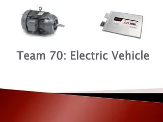
CAM Mover system : Smart Motor SmartMotors from Animatics Corporations 2 for undulator segment translation. 5 for cradle assembly camshafts. http://www.animatics.com RS-232 Integrated controller/drive DC Servo motor
CAM Mover system : Linear transducer http://www.novotechnik.com Linear transducers (w/2-micron repeatability) from Novotechnik US, Inc. 2 for undulator segment translation and 8 for cradle assembly. With 16 bit readout, the resolution is 0.15 micron. Rotary transducers (w/0.004 degree repeatability) from Novotechnik US, Inc. 5 for cradle assembly camshafts. With 16 bit readout, the resolution is 0.005 degree.
Mover system status and FY06 Goals • Asyn/EPICS/Linux embedded IOC SmartMotor development : Complete • Motor drive unit test : Complete • ADC sensor development : Complete • Cam Shaft motion control and position feedback system development: Feb ‘06 • Client (calibration) tools development : June ‘06 • Verification environment: July ‘06 • Network management: ?? • Configuration management: ??
Support SUT Integrate EPICS based motion of the undulator axis (Feb 06) Nail down temperature monitoring scope and implement (June 06) Determine feasibility of in-vacuum high precision stages (nano-motion) We did some work in FY05 to characterize these stages; now we have to make them work with one of our “standard” motion control solutions (this requires adding activities) Support BPM testing at the APS Liaison to APS/Controls Integrate with APS timing system Analysis software (ADC) Complete cable routing and thermal analysis of the Undulator hall Power supplies for the quads/correctors Other Undulator Controls tasks on the horizon
Supporting Slides • Undulator design supporting Slides Follow
Undulator design changes • Extended wedge • Roller bearing • High ratio gearbox
Supporting Slides • Cable and thermal mapping slides follow