Download
1 / 25
260 likes | 428 Views
P3K Integration and Test Review. Stephen Guiwits P3K System Computers and Electronics 273 Cahill September 22, 2010. Agenda. P3K Electronics Team Overview of the P3K Architecture RTC System DM System Cassegrain System Work Completed What has been built and tested Known Issues

E N D
P3K Integration and Test Review Stephen Guiwits P3K System Computers and Electronics 273 Cahill September 22, 2010
Agenda • P3K Electronics Team • Overview of the P3K Architecture • RTC System • DM System • Cassegrain System • Work Completed • What has been built and tested • Known Issues • Work Remaining
P3K Electronics Team • Dean Palmer (JPL) • Antonin Bouchez (CIT) • Ernest Croner (CIT) • Hector Rodriguez (CIT) • Stephen Guiwits (JPL)
RTC System • Cluster of 10 PC’s in the computer room • Real-time calculations performed on 16 Nvidia GPU’s • PC 0 provides the servo control, central scheduling, control of the cluster, and high-speed data link to mirror drivers (HODM, LODM, TTM) • PC 1 – PC 8 provides GPU calculations • PC 9 is dedicated to telemetry recording • Cluster communication provided by the high speed Quadrics switch • 1064 Mbytes/s • 900 MB/S Sustainable • RAID System • RAID 0 • Two partitions (High speed data / All other data) • Optical Splitter provides duplicates frames to all 8 PC’s • All PC’s running Red Hat Enterprise Linux 5 • Kickstart set up for automated, repeatable installations • Custom RPMS built and tested specifically for P3K
HODM System • 8 Xinetics Drivers • Two full height racks (30U / 52.5”) • Currently air cooled • Liquid cooled on telescope • Serial Interface • Slow speed control • SOR-422U Interface • High speed control • Custom built electronics
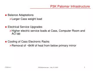
Cassegrain System • Rack 1 (currently being changed for liquid cooling) • Liquid cooled • Low order DM electronics • WFS Camera • PC
Cassegrain System • Rack 2 • Air cooled • Motion controllers • Motor cable break-out box • Laser sources
Work Completed • RTC System (hardware, cabling, communications, kickstart) • HODM System • Hardware • Communications • Cassegrain Racks • Required lab components working • During lab testing we didn’t have (or require) all components as some were still being used in the original AO system • Communications • Control Computer • Software and hardware installed and configured • Currently used for running the AO system in the lab
Xinetics GenIII Drivers • Stability • Idle issues. Random driver will fault when powered on and not used (no voltage applied) • Work well after running • Multiple runs over a 48+ hour period • Thousands of commands sent to date • Serial interface has several bugs. We have been able to work around them so far.
High Speed Interface • Random data in one quadrant of the mirror • Doesn’t appear all the time • Working on finding out what the cause is • Possibly in the FPGA portion of the high speed interface • SOR-422U issue within the driver
Work Remaining • Move current hardware in CIT lab to Palomar • LODM interface • TTM interface • Cabling • HODM • WFS • Motion Control The following is a summary of work remaining to achieve first light
Move CIT lab to Palomar • Ship everything currently in the lab at Caltech to Palomar • Set up electronics and test with Palomar infrastructure (power, communications) and verify things are working as expected • Integrate electronics with the components currently on the AO bench and verify things are working as expected
Low Order Mirror Electronics We require a new board to be built for communications with the low order deformable mirror electronics due to architecture changes. This will be a drop in replacement board allowing us to reuse our existing electronics and cabling with minor modifications. Steps required to complete: • Design receiver PCB required to take the place of the current board - done • Send PCB out for fabrication - done • FPGA programming • Test completed board • Retrofit current low order amplifier boards • Assemble into rack enclosure
Tip Tilt Mirror Electronics We require new electronics to communicate with our tip tilt mirror. These electronics will receive data from one of our RTC machines and send the data to the mirror. Steps required to complete: • Design PCB - done • Send out PCB for fabrication - done • Procured TTM PCB mounting enclosure - done • Program FPGA – in progress • Send TTM PCB mounting enclosure out for engraving • Procure power source for mirror electronics • Test completed board • Assemble into mounting box • Design and build interim cable
Cabling In order to provide a save and efficient way for the Mt. Palomar staff to cable up the new system, we had to design a new cabling scheme for our new electronics. The HODM, Motor cables, and WFS cables require design and fabrication. • HODM • Xinetics shipped 99 Omnetics cable with the electronics. These cables are very fragile and take hours to connect • We will: • Reduce cables from 99 to 16 • Reduces installation from < 2 hours to ~1 minute • Use Hypertronics connectors • 100,000 mating cycles • Low insertion force • ½ turn quick disconnects
Cabling • Motor cables We will: • Reduce 19 cables of different type connectors to 2 connectors (1 signal, 1 power) • Reduces installation time from < 20 minutes to ~ 1 minute • Use Hypertronics connectors • 100,000 mating cycles • Low insertion force • ½ turn quick disconnects • WFS cables • The wave front sensor camera came with a set of cables that are to short for use on the telescope as well as tedious to connect We will: • Reduce 19 cables of different type connectors to 2 connectors • Reduces installation time from < 20 minutes to ~ 1 minute
Cabling • High order deformable mirror (HODM) cabling • Bench interface • Design cable box enclosure • Plan integration of 99 Omnetics cables to the Mirror Interface Boards (MIB) – Spreadsheet mapping connections • Modify 99 Omnetics cables and wire into MIB • Cut cables to appropriate length • Soldering open end to connectors located on the MIB • Test signals from cable MIB • Assemble boards/cables with HODM bench enclosure • Rack interface • Complete DIB cable design • Design mounting box for the Driver Interface Boards (DIB) • Assemble boards with support and enclosure in the racks
Cabling • HODM Cabling (Continued) • DM cables (16) • Send out for fabrication - done • Test finished 30’ DM cables • Motor cabling • Plan integration of motors into two cables • Signal Cable • Power cable • Send motor cables out for fabrication • Procured the long lead items ahead of time - done
Cabling • Motor cabling (Continued) • Bench interface • Design bench side enclosure box • Complete wiring design between motor connectors and Hypertronics cables • Assemble wiring and connectors into bench enclosure • Rack interface • Reusing the current motor interface box • Design wiring inside the enclosure • Assemble wiring and connectors in enclosure in rack • Test finished 30’ motor cables
Cabling • High Order Wavefront Sensor Cabling • Came with vendor supplied cables • Need a faster way to hook up WFS cables • Designed interfaces for easy installation • Bench and rack interfaces • Order parts – done • Assembling cables – in progress • Design and fabricate rack side interface panel • Part of the enclosure design • Test final cables