Download
1 / 26
270 likes | 576 Views
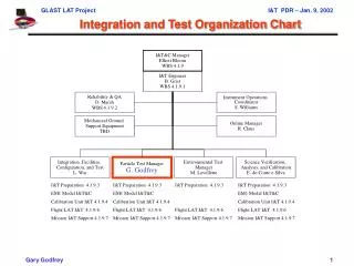
HMI00372. Integration, Test, and Verification. Michael Levay Integration and Test Lead michael.levay@lmco.com 650-424-4046. Integration and Test – Agenda. Review of Driving Requirements Instrument Integration GSE Verification Approach Functional Test Environmental Test Flow

E N D
HMI00372 Integration, Test, and Verification Michael Levay Integration and Test Lead michael.levay@lmco.com 650-424-4046
Integration and Test – Agenda • Review of Driving Requirements • Instrument Integration • GSE • Verification Approach • Functional Test • Environmental Test Flow • Test Facilities • Open Issues
Driving Requirements • Provide facilities, equipment, and personnel to verify system functional performance • Demonstrate instrument compliance to environmental requirements: Vibration, Acoustics, Shock, TB/TV, EMC • Perform test/qualification of selected engineering model Sub-assemblies/Subsystems • Mechanism life test (shutters and hollow motors) • Engineering Test Unit (ETU) filter oven performance test • (OP) Structure Model (SM) test • SM Oven • SM Telescope • Prototype alignment mechanism (functional) • Prototype door mechanism (functional) • Engineering model ISS • Perform testing and characterization of selected flight model Sub-assemblies/Subsystems • Telescope, ISS, filter oven with optics, focal planes • Support integrated spacecraft level testing at GSFC
Integration Approach • Mechanical/Optical • Integrate major subsystems outside the OP • Telescope • Filter Oven • Focal Plane Assemblies • ISS • Subsystems and sub-assemblies first integrated to an “identical” non-flight baseplate • Bench is in clean tent • Sub-assemblies and subsystems are aligned and focused on the NF baseplate • Sub-assemblies and subsystems are transferred to OP with little additional adjustment • Assembly sequence is rehearsed during SM build-up • Stimulus telescope system allows focusing to vacuum positions in air • Electrical • Brass board system with at least one of each type of board for design verification • Brass board is then used for flight board testing and software development • During initial phase of integration, brass board electronics may be shared between flight board testing, software development, and flight system integration • Software • Software builds match schedule requirements for board/box level electronics test • Software acceptance dry run uses BB electronics and mechanisms • Two subsequent complete Software acceptances planned at the beginning and end of environmental testing • Regression testing if/when major software modifications occur during the test flow
Telescope Build-up Window/Filter Calibrate filter Integrate &align telescope subsystem Telescope structure Verify optics performance Optics fabrication
Filter Oven Build-up Lyot element fabrication Assemble/calibrate Lyot filter Assemble/alignLyot cells Michelsons fabrication Assemble/testfilter oven system Test oven & controller Oven & controller fabrication Test mechanisms Fabricate mechanisms Integrate mechanisms and waveplates/polarizers Fabricate polarizers/procure waveplates Test Waveplates and Polarizers
Electrical and Software Build-up BAE Flight model integration Develop SUROM software Procure FM RAD6000’s SUROM software Test Flight electronics build and test Procure EM RAD6000 Design/Fabricate Brassboard interconnect and Bridge Flight software development on BB electronics Flight software test on BB electronics Test flight boards with BB electronics Flight software acceptance dry run on BB electronics Test BB electronics Design/Fabricate BB Electronics
Focal Plane Assembly Build-up Flight focal plane integration and test at LM Flight sensor evaluation at LM Sensor evaluation GSE procurement at LM Flight sensor program (e2v) Development sensor program (e2v) Development camera program (RAL) Flight camera program (RAL) Development camera integration and test (RAL) Flight camera test (RAL) Development camera to LM for electrical and software test
HMI Assembly & Integration Flow Install focus & polarization analyzers Install and align fold mirrors and beamsplitters BB electronics available for test support Install & align telescope Install alignment mechanism Install flight ISS Install shutters and focal plane optics Install filter oven system Install front door Install focal plane assembly & camera Install misc. hardware (baffles, etc.) Install flight electronics and software Spacecraft integration and test HMI functional testing HMI calibration HMI environmental testing Ops and Analysis Launch and Commissioning
GSE • Mechanical • Lifting Fixtures • Shipping containers and handling fixtures (OP and HEB) • Rotation fixture (for access to underside, e.g., MLI installation) • Vibration fixtures (OP and HEB) • Alignment stand • Protective covers (Radiators, Instrument, CEB) • Subsystem support fixtures (telescope, oven) • TV/TB GSE (hot/cold boxes, support structure, MLI) • Optical • Stimulus telescope • Supply a reference beam for locating optical component to their final vacuum positions • Provide method for testing the ISS • Provide a method for integration optics in air to their vacuum positions (Air to Vacuum correction capability) • Tunable laser at 6173 • Electrical • Spacecraft simulators (GFE) • EGSE workstations • IEEE control instrumentation
Verification Approach • Verification items consist of • Spacecraft driven resource limitations • Science driven performance requirements • The approach is to demonstrate compliance to requirements at the integrated instrument level • Verification will show that the instrument is capable of producing the measurements required to realize the science requirements • Instrument level verification will demonstrate integrated optical, mechanical, electrical and sensor performance using solar and synthetic targets. • Measurements of individual elements and sub-assemblies will be performed to gain confidence that the integrated instrument will perform as required • The SM and Spacecraft Interface Simulator will be used to show compliance to interfaces and resource limitations
Verification Approach • HMI formal verification will be per the requirements in the functional specification. • The spec includes items that can be verified at the integrated instrument level • The Test and Verification Plan will define test activities and plans beyond those that are required for verification in order to give NASA insight into sub-assembly level testing, life testing, etc. • Most testing will occur at LMATC or other LM facilities • Optical tables, heliostat feed, vacuum test facilities are already available • Project specific equipment yet to be purchased include stimulus telescope, lifting and handling fixtures, shipping containers, etc. • Some environmental testing may be sub-contracted/purchased
Functional Testing • The tests will be run with controlled STOL procedures (STOL, Systems Test & Operations Language). • The aliveness test will require less than 30 minutes and will test the major subsystems. • The Short Form Functional Test (SFFT) will require a few hours and will test all subsystems but not all paths. It will not require the stimulus telescope. • The Long Form Functional Test (LFFT) will require ~8 hours and will test all paths and major operational modes (the SFFT is a subset of the LFFT). The LFFT will require the use of the stimulus telescope and perhaps the laser. • Comprehensive Performance Test (CPT) sets the baseline at the start of the Environmental Test Program and is performed again at the end. This test will require several days and will contain extensive optical and functional testing of the integrated instrument and will test all capabilities including those not normally used during operations. • Special Performance Tests (SPT) are tests that measure a specific aspect of the HMI performance. These are detailed tests that require the stimulus telescope, lasers, sunlight, or other special setups. They are performed only a few times in the program. Some tests require operating in vacuum
Part P A part is an individual end item. Parts are assembled into assemblies. Examples of parts are: CCD, filter, lenses and mirrors without mounts Assembly A An assembly is more than one part. Examples of assemblies are: electronics boards, shutter or hollow core motors, beam splitters and optic assemblies Subsystem S A subsystem consists of multiple components. Examples are: an imager path, i.e. the ISS, telescope, or electronics box Instrument I The instrument is the combination of the OP, electronics boxes, harnesses and most or all other flight hardware. Model M The unit under test is a non-flight model Levels of Assembly
Comprehensive Performance Test Special performance test dry runs Long Form Functional Test Long Form Functional Test Long Form Functional Test Long Form Functional Test Special performance test in air Comprehensive Performance Test Thermal Vacuum Alignment, TB/TV De-prep Environmental Test Flow Alignment and Acoustics Prep IT & Cal EMI/EMC Cal SFFT Random Vibration Alignment, Vibration Prep Acoustics Sine Sweep SFFT Alignment and TB/TV Prep Alignment Shock Prep Shock SFFT Chamber Certification SFFT Special performance test in vacuum • Delivery Thermal Balance
Test Facilities • LMSAL Sun Laboratory • 1500 sq ft room with 4 separate bays • Blackout curtains separate the areas • HMI will use about ½ the area • Heliostat for natural sunlight testing • Includes class 10, 000 clean tent • Adequate for buildup on GSE bench and flight box • LMSAL Astro Lab - Vacuum Chamber • 1.5 m diameter x 5.5 m length vacuum chamber used for other projects • Heliostat feed used for optical tests during thermal vacuum test • Heliostat upgrade in progress (LM fixed asset) • Plan to use hot/cold box method rather than cold shroud • Method proven on other programs • LMSAL Optical Characterization Facilities and Equipment • Cary Spectrophotometer - transmittance and reflectivity measurements • Zygo Interferometer – wave front error and flatness measurements • Eschelle Spectrograph - wavelength standard for filter calibration • HeNe (6328 A)and tunable lasers
LMSAL Sun Laboratory Clean Room Class 10,000 Flight Buildup Heliostat Non- Flight Base Plate Clean Tent Class 10,000 EGSE Room 110
Class 10,000 Clean Tent EGSE Consoles Heliostat Fold Mirror
Thermal Vacuum Setup Class 1,000 Clean Tent Clean Tent Class 100,000 MGSE Rails LMSAL Room 116 OP Heliostat HEB Spectrograph Lab Room 117
Spacecraft I&T • HMI will have a presence at spacecraft integration and test sites • We intend to participate in all significant test and integration activities that involve HMI • There are no items that require late installation or reinstallation • There is a purge port • We expect to be able to purge whenever we choose • We can supply the purge equipment but expect NASA to supply the purge gas • We will supply whatever lifting and handling mechanical GSE that attaches directly to HMI • (Electrical) test connector will be used for troubleshooting only • There are a few non-flight items (protective covers for radiators) • There will be stimulus telescope system that we will use for optical health checks • We intend to use this through a window in vacuum • HMI includes an LED for camera aliveness tests • We understand that we will test HMI using our automated (STOL) test procedures on our GSE during spacecraft testing.
Open Issues • Integration, test, and verification concepts are at PDR level, so there are no significant open issues. • There are several items that require resolution prior to CDR. These include: • Agreement with NASA on detailed contents of the specification • Implement HMI verification database (modification to existing capability) • Detailed description of the interface between Stanford and LMSAL supplied test and calibration software • Baseline design for stimulus system including air-to-vacuum adjustment capabilities • Update Integration, Test, and Verification Plan