Download

1 / 75
800 likes | 853 Views
Testing of transformers. Transformer Tests. The performance of a transformer can be calculated on the basis of equivalent circuit.The four main parameters of equivalent circuit are: - R 01 as referred to primary (or secondary R 02 )

E N D
Transformer Tests • The performance of a transformer can be calculated on the basis of equivalent circuit.Thefour main parameters of equivalent circuit are: • - R01 as referred to primary (or secondary R02) • - the equivalent leakage reactance X01as referred to primary (or secondary X02) • - Magnetising susceptanceB0 ( or reactance X0) • - core loss conductance G0 (or resistance R0) • The above constants can be easily determined by two tests • - Oper circuit test (O.C test / No load test) • - Short circuit test (S.C test/Impedance test)
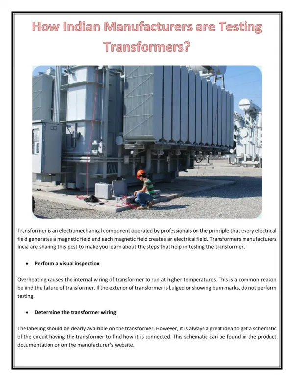
Open-circuit Test • In Open Circuit Test the transformer’s secondary winding is open-circuited, and its primary winding is connected to a full-rated line voltage. • Usually conducted on H.V side • To find (i) No load loss or core loss (ii) No load current Io which is helpful in finding Go(or Ro ) and Bo (or Xo )
Short-circuit Test • In Short Circuit Test the secondary terminals are short circuited, and the primary terminals are connected to a fairly low-voltage source • The input voltage is adjusted until the current in the short circuited windings is equal to its rated value. The input voltage, current and power is measured. • Usually conducted on L.V side • To find (i) Full load copper loss – to pre determine the efficiency (ii) Z01 or Z02; X01 or X02; R01 or R02 - to predetermine the voltage regulation
Voltage regulation of a transformer recall Secondary voltage on no-load V2 is a secondary terminal voltage on full load Substitute we have
Transformer equivalent circuit • To determine the voltage regulation of a transformer, it is necessary understand the voltage drops within it.
Cont.. • Ignoring the excitation of the branch (since the current flow through the branch is considered to be small), more consideration is given to the series impedances (Req +jXeq). • Voltage Regulation depends on magnitude of the series impedance and the phase angle of the current flowing through the transformer. • Phasor diagrams will determine the effects of these factors on the voltage regulation. A phasor diagram consist of current and voltage vectors.
Cont.. • Assume that the reference phasor is the secondary voltage, VS. Therefore the reference phasor will have 0 degrees in terms of angle. • Based upon the equivalent circuit, apply Kirchoff Voltage Law,
Transformer Phasor Diagram When the power factor is unity, VS is lower than VP so VR > 0.
Transformer Phasor Diagram With a leading power factor, VS is higher than the referred VP so VR < 0
Transformer Phasor Diagram • For lagging loads, the vertical components of Req and Xeq will partially cancel each other. Due to that, the angle of VP/a will be very small • hence we can assume that VP/k is horizontal. Therefore the approximation will be as follows:
Transformer Efficiency • The Efficiency of the transformer is defined as the ratio of useful power output to the input power. • The input and the output power are measured in the same unit. Its unit is either in Watts (W) or KW. Transformer efficiency is denoted by Ƞ.
PROCEDURE: • Start the alternator with the help of prime mover (DC Motor). • Adjust the speed of the prime mover so that the alternator voltage frequency should be 50 Hz. • Vary the excitation of the alternator so that the required voltage builds across the armature (Say 230 V between line and neutral). • Note down all meter readings. • Repeat the above steps for different frequencies by changing the speed of the prime mover (With Speed control of DC Shunt motor by Armature control or Field Control). • Repeat step 6 for different frequencies of the alternator say 46 Hz, 48 Hz, 50 Hz, and 54 Hz keeping V/f ratio constant. • Plot the graph between V/f and core losses of the transformer.
Necessity Of Parallel Operation Of Transformers • Why parallel operation of transformers is needed? • Increased Load: • Non-availability of large transformer: • Increased reliability: • Transportation is easier for small transformers:
Conditions For Parallel Operation • Voltage ratio of all connected transformers must be same. • The per unit (pu) impedance of each transformer on its own base must be same. • The polarity of all connected transformers must be same • The phase sequence must be identical of all parallel transformers. • The short-circuit impedances should be approximately equal
the transformers are connected in parallel when the load is more than the rating of the individual transformers. • several smaller units are operated in parallel which share a common load. • in the fig. we can see that the primary windings are connected to the supply bus bars while the secondary are connected to load bus bars
PARALLEL OPERATION OF TWO IDEALTRANSFORMER
phasor diagram • now we will consider ideal case of two transformers having the same voltage ratio and their voltage triangles are equal in size and shape. • as seen the impedance voltage triangles of both the transformers is same .
theory • let us now consider the case of two transformers connected in parallel having equal voltage ratios. the two transformers are having no load secondary voltage same . • these voltages are in phase with each other. • this is possible if the magnetizing currents of the two transformers are not much different . • this is represented in the shown circuit.
The phasor diagram under this condition is shown . • The two impedances Z1 and Z2 are in parallel. • The values of Z1 and Z2 are with respect to secondary.
Parallel Operation of Transformers With unequal Voltage ratios
Parallel Operation of Transformers with Unequal Voltage Ratios • Now we will consider the case of two transformers working in parallel and having unequal voltage ratio. This is shown in the Fig. 1. • The voltage ratios of the two transformers are not equal. The parallel operation under this case is still possible. But as seen previously there would be a circulating current under no load condition.
Derivation for currents Let us consider voltage ratio of transformer 1 is slightly more than 2. So that induced e.m.f.. E1 is greater than E2. Thus the resultant terminal voltage will be E1 - E2 which will cause a circulating current under no load condition. Ic= (E1 - E2)/(Z1 + Z2 ) From the circuit diagram we have, E1 = V2 + I1 Z1 E2 = V2 + I2 Z2 Also, IL = I1 + I2 V2 = IL ZL = ( II + I2 ) ZL E1 =(I1 + I2) ZL + II Z1 .........(a) E2 =(I1 + I2 ) ZL + I2 Z2 .......(b) Subtracting equations (a) and (b) we have, E1 - E2 = I1 Z1 - I2 Z2 I1 = ((E1 - E2) + I2 Z2) /Z1
Cont.. Subtracting this value in equation (b), ... I2 = (E2 Z1 - (E1 - E2)ZL) / (Z1 Z2 + ZL (Z1 + Z2)) Similarly, I1 = (E1 Z2 + (E1 - E2)ZL)/ (Z1 Z2 + ZL (Z1 + Z2)) Adding the above equations, I1 + I2 = (E1 Z2 + E2 Z1) / (Z1 Z2 + ZL (Z1 + Z2)) .............(c) But IL = I1 + I2 Load voltage, V2 = IL ZL Dividing both numerator and denominator of equation (c) by Z1 Z2,
AUTO TRANSFORMERS
CONSTRUCTION: In an autotransformer , only one winding is wound on a laminating magnetic core while in 2 winding , two windings are wound. the single winding of the autot/f are used as primary and secondary. the part of the winding is common to both primary and secondary. the voltage can be stepped down or up using an autotransformer. accordingly they are classified as step up autotransformers step down autotransformers
in the fig the convectional two winding t/f and the step up and down t/f are shown . • in step down t/f the entire winding acts as a primary while the part of the winding is used common to both primary and secondary. • thus ab forms the primary having n1 turns while bc forms secondary with n2 turns.
THE CURRENT DISTRIBUTION IN STEP UP AND STEP DOWN AUTO T/F ARE SHOWN AS BELOW : transfprmation ratio of a.t/f: neglecting the losses the leakage reactance and the magnetizing current,the transformation ratio of an auto t/f can be obtained as , k=v2/v1 =i1/i2 =N2/N1
k is greater than unity for step up auto t/f while k is less than unity for step down auto t/f. • due to the use of single winding compared to the normal two winding t/f for the same cpacity and voltage ratio, • there is substantial saving in copper in case of auto t/f. • COPPER SAVING IN AUTO T/F: • for any winding the cross section o winding is proportional to the current i. • while the total length of the winding is proportional to the number of turns n . • hence the weight of copper is proportional to the product og n and i. • while i=current of winding • n=number of turns of winding
CONSIDER A TWO WINDING T/F AND A STEP DOWN T/F AS SHOWN IN FIG . TWO WINDING TRASFORMER then let Wtw= total weight of copper in two winding t/f Wat=weight of copper in auto t/f Saving of copper=KWtwv for step down transformer Saving of copper=1/K *Wtwv for step up transformer
POWER TRANSFER IN AUTO T/F : it is mentioned earlier that the power input to an autotransformer gets transferred to the scondary by two ways , i.e, by electromagnetic induction by conduction consider a loaded auto t/f as shown . the current drawn form the supply is i1 while the input voltage is v1. • input power = v1i1 • while the load current id i2 at a load voltage v2 • output power=v2i2
now bc portion has n2 turns and acts as secondary. the current induced in this scondary due to transformer action is i2-i1 while secondary induced voltage is v2. • pt=power transferred inductively • =(i2-i1)v2=v2i2-v2i1 • k=v2/v1 = i1/i2 • pt=k.v1(i1/k - k.v1.i1) • =v1 i1- k v1 i1 • while the remaining power gets transffered directly that is, conductively as windings are electrically connected. PT=(1-K)V1 I1 = (1-K)INPUT POWER
VA RATING OF AYTO TRANSFORMERS: • let us compare the VA rating of two winding transformer and the VA rating of two winding transformer when connected as an auto t/f. for step down transformer • For step up transformer K is replaced by 1/K
CONVERSION OF TWO WINDING T/F TO AN AUTO T/F : • consider a two winding t/f with the polarities as shown . the t/f turns ratio is 1:1 and v2=v1=400v. • this t/f can be converted to an auto t/f in two ways • additive polarity • subtractive polarity • the primary and secondary windings can be connected in series with additive polarity as ashown.
the common point a which is common to input and output can be taken as the top of an auto t/f. • the corresponding auto t/f is as shown . • thus if input is v1 then the output is v1+v2 due to additive polarities • with common point a at the bottom auto t/f can be shown .
SUBTRACTIVE POLARITY : the primary and secindary windings can be connected in series opposition as shown in fig. • the common point a which is common to input and output can be taken as the top of the auto t/f as shown in fig. • thus if the input is v1 then the output voltage is v1-v2 due to subtractive polarities.
ADVANTAGES OF AUTO TRANSFORMERS : • copper requried is very less. • the efficiency is higher compared to two winding t/f. • the size and cost is less compared to two winding transformer. • the resistance and leakage reactance is less compared to two winding t/f. • the copper losses are less. • due to less resistance and leakage resistance the voltage regulation is supirior than the two winding t/f. • va rating is more compared to two winding. • a smooth and continious variation of voltage is possible.
LIMITATIONS OF AUTO TRANSFORMERS : • low impedance hence high short circuit currents for short circuits on secondary side. • if a section of winding common to primary and secondary is opened full primary voltage appears across the secondary resulting in higher voltages on secondary and danger of accidents. • no elecricalseperation between primary and secondary which is risky in case of high voltage levels . • economical only where the voltage ratio is less than 2 .