Download
1 / 18
180 likes | 257 Views
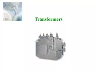
Transformers. Transformers are some of the most efficient machines that can be built, with efficiencies exceeding 99%. Only simple machines (levers, inclined planes, etc.) are more efficient. Transformers have no moving parts, making them extremely reliable.

E N D
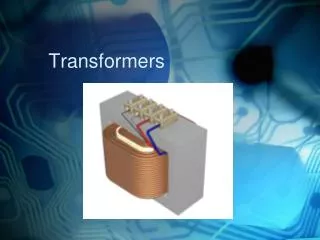
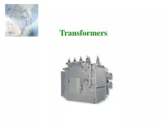
Transformers Transformers are some of the most efficient machines that can be built, with efficiencies exceeding 99%. Only simple machines (levers, inclined planes, etc.) are more efficient. Transformers have no moving parts, making them extremely reliable. The electrical insulation is about the only component of a transformer that can fail.
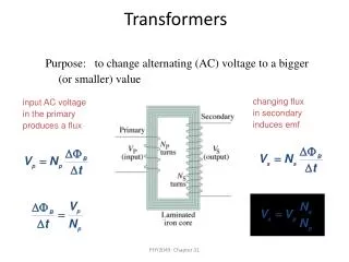
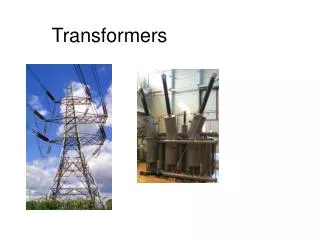
Transformers Devices comprised of two electric circuits (isolated from each other) linked by a magnetic circuit. When a time-varying current flows in the first electric circuit, a time-varying magnetic flux is established in the magnetic circuit. When this time-varying flux links the second electric circuit, a time-varying voltage is induced, per Faraday’s Law.
Magnetic Circuits Magnetic circuits are somewhat analogous to DC electric circuits. Electrical Quantity Magnetic Quantity Voltage (volts) Magnetomotive Force (ampere-turns) Current (amperes) Magnetic Flux (webers) Resistance (ohms) Reluctance (ampere-turns per weber) V = I R =
Magnetic Properties Transformer steel is made of alloys very different from structural steels (low in carbon, high in silicon). Each molecule of the steel core is a magnetic dipole (think of a tiny bar magnet). Normally, the north and south poles (magnetic domains) are randomly aligned to give no net magnetic effect. But if the domains are aligned, magnetism is achieved. The alignment of the magnetic domains is called magnetic flux.
Magnetic Materials Starting from zero, gradually increase the current flowing through a coil. This increases the magnetic field (H) surrounding the coil. As H increases, the magnetic flux density (B) also increases – almost linearly at first, but eventually undergoes saturation.
Magnetic Materials When the current is decreased, H also decreases. But B decreases at a lesser rate than at which it increased. There is a tendency for aligned magnetic domains to remain aligned. When H reaches zero, the remaining B is called the residual magnetism or residual induction.
Magnetic Materials Further decreasing the current (becoming negative) drives the flux density to zero. The point at where B=0 defines the coercive force of the material. A further decrease in current leads to a negative saturation point.
Magnetic Materials Increasing the current increases B, but in a non-linear way. The curve passes to the right of the origin, but intersects itself at the positive saturation point. This closed path is known as a hysteresis loop.
Magnetic Materials The area inside the hysteresis loop represents the energy lost per cycle in the magnetic material. This energy loss shows up as heat.
Laminated Steel Insulated thin steel sheets called laminations are stacked to form a magnetic core. The laminations reduce eddy currents.
Winding Conductor Transformer winding conductor is usually rectangular in cross-section, and is insulated with Kraft paper. The conductor material can be copper or aluminum. Copper is mechanically stronger, so is preferred for larger transformers. Smaller transformers often use aluminum windings to reduce cost.
Ideal Transformers Example: Redraw the diagram below twice as a single electric circuit, the first time reflected to the high-voltage circuit, and the second time reflected to the low-voltage circuit.
Ideal Transformers Reflected to the high-voltage circuit:
Ideal Transformers Reflected to the low-voltage circuit:
Real Transformers Must account for: • Resistance in the winding conductors • Power (I2R) losses • Leakage reactance • Flux produced by one winding that does not link the other • Energy to magnetize core • Alignment of magnetic domains in core steel • Electrical losses in core • Hysteresis and eddy currents