Download
1 / 93
950 likes | 1.16k Views
MOBILE COMMUNICATION THROUGH CDMA TECHNOLOGY. CDMA OVERVIEW. Presentation by- Arunabh Kumar & Pravir Kumar with ECE Final Year,R.P.S.I.T Patna.

E N D
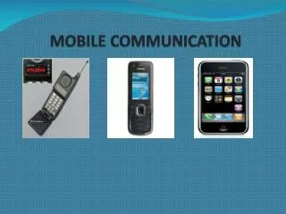
MOBILE COMMUNICATION THROUGH CDMA TECHNOLOGY
CDMA OVERVIEW Presentation by- Arunabh Kumar & Pravir Kumar with ECE Final Year,R.P.S.I.T Patna.
SAHID MASWOOD (HRD PATNA) SIGNATURE COMMENTS: B.C.NAYAK (CDMA LEAD) SIGNATURE COMMENTS:
Contents • Acknowledgement • Mobile communication history • Multiple Access methods • GSM And CDMA • Departments of CDMA • R F Overview • Switch Overview • Call Flow • Signaling • POI • NLD/ILD • Transportation Overview • Fixed Access • Out-side Plant • Advantages, Disadvantages
Acknowledgement We got this great opportunity to present project on CDMA Overview prepared on the basis on four week training in Reliance Info COM Pvt. Ltd. Patna. We owe our sincere thanks to • Shahid Maswood (HRD Patna) • B. C. Nayak (CDMA LEAD) • Manoj Sinha (MCN Cluster in charge)
We express sincere thanks to the management at RELIANCE INFOCOMM Pvt. Ltd. Mr. R.N.Rathore &MCN Patna, in particular to Mr. Saurav Chaurasiya,Mr. Amar Nath Prasad & Mr. Dhananjay Kumar, all are arranging and scheduling our training for 4 weeks. Without their generous support, We could not have completed our training so efficiently. At last, we are really thankful to Mr. Himanshu Shekhar & Miss. Priyanka Priya without there co-operation ,it couldn’t be possible.
3rd. Generation (2000s) 2nd. Generation (1990s) Digital 1st.Generation (1980s) GSM DECT DCS1800 CT2 PDC PHS IS-54 IS-95 IS-136 UP-PCS Analog NMT CT0 TACS CT1 AMPS IMT-2000 CDMA2000 W-CDMA MOBILE COMMUICATION HISTORY
1946 Mobile communication Appeared St. Louis USA 1946to1970 Slow growth of mobile networks all over world. 1970 BELL LAB introduced Cellular Principle. 1979 AMPS System in US Analogue technology used. Technologies incompatible. Modules cumbersome & heavy. 1980s TACS & NMT systems introduced by Europe & Nordic countries. 1990s Digital Systems introduced.
1946- 1960s1980s 1990s 2000s Appeared 1G 2G 3G Analog Digital Digital Multi Multi Unified Standard Standard Standard Terrestrial Terrestrial Terrestrial & Satellite
Analog Systems (1st Generation) • AMPS: Advanced Mobile Phone Service (US, 800 MHz Band) • TACS: Total Access Communication System (UK , 900 MHz Band) • NMT450: Nordic Mobile Telephone Service (Scandinavian, 450 MHz & 900 MHz Band)
Digital Systems ( 2nd Generation) 1990’s • DAMPS: Digital AMPS (US, 800 MHz Band, IS-54 IS-136) • CDMA: Code Division Multiple Access System (US, 900 MHz Band, 1S-95) • GSM: Global System For Mobile Communication. (Europe, 900 / 1800 MHz Band)
Requirements for 3rd generation Mobile Systems • High Capacity • Tolerance for interference • Privacy • Tolerance for fading • Ability to various data rate transmission • Flexible Quality of Service (QoS)
Multiple access method Multiple Accesses: *Multiple Accesses is the simultaneous use of a communication system by one or more user. *Each user’s signal must be kept uniquely distinguishable from user’s signals to allow private communications on demand. *Users can be separated many ways: .Physically: on separated wires . By arbitrarily defined “channels” established in frequency, time, or any other variable imaginable.
155 Mbps • Very High Data Rate up-to 155 Mbps. • No Mobility. Fixed Wireless Data Rate • High Data Rate up-to 54 Mbps. • Little Mobility. Data Rate VS Mobility 54 Mbps W-LAN • Moderate Data Rate. • High Mobility. Cellular • Moderate Data Rates. • Very long distances. • very high Mobility. 2 Mbps In-door Out-door 3 G Satellite Vehicular. 2 G Mobility Cellular Technologies
FDMA Frequency Division Multiple Access • Oldest &most familiar method of radio communication • Each user is assigned with unique channel of frequency • Acts as private freq. for its call duration • As call terminates, the channel is released and available for new call. • Number of users are less
TDMA Time Division Multiple Access • A user’s channel is a specific frequency • But only allotted for a certain duration • It belongs to the user for certain time slots in repeating sequence. • Numbers of users are much greater • Groupe Special Mobile (GSM) uses this technique
CDMA Code Division Multiple Access • Each user has specified frequency for all time • Each user has been given a unique code pattern • From these codes connections are identified. • This unique code is buried within a shared signal, mingled with other user’s code patterns. • If a user’s code pattern is known, the presence or absence of their signal can be detected, thus conveying information. • Numbers of users are very large
In Technology CDMA Has Plus Point Over GSM, Why? Because • CDMA is faster • CDMA is more secure • Connection on a CDMA network will never get dropped when moving from cell to cell • CDMA base stations cover a large area
1 Billion GSM Subscriber’s To CDMA’s 270 Million • GSM replaced archaic analogue system • Late appearance of CDMA • Adopting CDMA means paying royalty to QUALCOM • World standard for mobile communication • Availability of international roaming
FUTURE’S TECHNOLOGY • GSM & CDMA both are moving towards improved technology based on CDMA technique • These techniques are Wideband-CDMA & CDMA 2000.
What is cell? A cell is a small area of service within a city, serviced by its own antenna. Frequency Reuse In CDMA- All users use same frequency Universal frequency reuse applies to the users in the same cell as well as to those in others Complicated reuse pattern is not necessary R F OVERVIEW
Spread Spectrum Concept 1800 1850 1910 1930 1990 2000MHz Cell TX m Mobile TX User 1 Code 1 User 2 Code 2 User 3 Code 3 Code n User n Spread spectrum uses much larger slice(1.25MHz) of the available bandwidth. Same slice is used for all user with no time multiplexing but user is assigned with a different code of to uniquely identify them.
CDMA Cellular Spectrum 849MHz 824MHz 835MHz 845MHz A” A B A’ B’ 846.5MHz 825MHz REVERSE LINK 869MHz 880MHz 894MHz 890MHz A” A B A’ B’ 870MHz 891.5MHz FORWARD LINK
Band Of CDMA • The 850MHz CDMA band is most popularly used all over the world • This band works between 824-849MHz used for the Reverse link communication 869-894MHz used for the Forward link communication each of 25MHz. The total band of 25MHz is divided into small channels of 30KHzeach.An actual CDMA carrier will be using a multiple of the 30KHz channels. This means for an actually utilized bw of 1.23MH will need 41*30KHz channels. Relationship between the channel numbers and actual freq. Reverse link frequency =(825+N0.03)MHz Forward link frequency=(870+N0.03)MHz N=CDMA Channel Number
Spread Spectrum Concept • Spread spectrum uses much larger slice (1.25 MHz) of the available bandwidth. Same slice is used for all users with no time multiplexing but each user is assigns with a different code to uniquely identify them. • CDMA uses a modulation technique called “Spread Spectrum” to transport a narrow band voice signal over a wide bandwidth channel .The wide bandwidth for IS-2000 is 1.23 MHz . • The CDMA modulation technique uses three methods for spectrum spreading: . frequency hopping (FH) . time hopping (TH) . direct sequence (DS) • While FH is more popular in CDMA system used for military purpose in commercial CDMA system DSSS is popularly used.
Direct Sequence-Spread Spectrum (DSSS) Techniques • CDMA is a scheme in which multiple users are assigned radio resources using the DSSS techniques. • Although all users are transmitting in the same RF band, all users’ arte separated from each other via the use of orthogonal codes (Walsh Code). • Each user has full time use of the entire spectral allocations. • Each user’s signal is spread over the entire bandwidth and codes so as to appear like broadband noise to every other user.
Spreading System In a spread system the data information signal, b(t), is multiplied by a wideband signal, c(t), which is the output signal of the Direct Sequence (DS) generator – a pseudorandom noise (PN) output signal. The signal which will eventually be transmitted, y(t) = b(t) c(t), will occupy bandwidth far in excess of the minimum m bandwidth to transmit the data information. Spreading Gain or Processing Gain (G) = Tb/Tc, Where, Tb is the bit interval of the Information steam & Tc is the bit interval of the DS stream. Tc is also called Chip Time .
The Processing Gain & Capacity Relation • CDMA spreading gain consider a user with a 9600 bps Vocoder talking on a CDMA signal 1,228,800 Hz wide. The processing gain is 1228800/9600 = 128, which is 21 db. . Shannon’s work suggests that a certain bit rate of information deserves a certain bandwidth .If one CDMA user is carried alone by a CDMA signal, the processing gain is large (roughly 21 db for an 8k vocoder). . Each doubling of the number of users consumes 3 db of the processing gain. . Somewhere above 32 users, the signal-to-noise ratio becomes undesirable and the ultimate capacity of the sector is reached. . Practical CDMA systems restrict the number of users per sector to ensure processing gain remains at usable levels.
WALSH CODES • 64 are available • 64 Chips long – lasts 1/19200 sec • mutually orthogonal • The user signal (or control channel) is multiplied by the Walsh code. • The Walsh code provides each user or channel with an unique identifier and, in DS spreading, spreads the frame across the entire 1.23MHz bandwidth.
PN SHORT CODES • one pair is used (I & Q) • 32 K long –lasts 26-2/3 ms, repeats 75x in 2sec. • Generated in 15 – bit tapped shift register. • Nearly self – orthogonal if compare out of sync • On the Reverse link it is used only for quadrature spreading without any offset or • The PN Short Code is used only for tracking the mobile that means to calculate the round trip delay or path delay for the mobile.
PN LONG CODE • only one is used • (2)42 – 1 chips long – lasts 40+ days! • generated in 42 – bit shift register. • Any short sample is nearly orthogonal with any other short sample. • Information about the long code is broadcast to the mobile station by the sync channel to help the mobile lock onto the base station and helps provide separation from other station. • It is used to scrambled the interleaved signal and provide additional security against interception and interference. • An additional advantage of the long code is that it allows the transmitter to use less power ,maintaining control over the ambient RF environment and increasing the overall capacity of the cell.
Steps evolved for signal transmission 1. A pseudo random code is generated, different for each channel& successive connections. 2. The information data modulates the pseudo random codes. 3. The resulting signal modulates the carrier. 4. The modulated carrier is amplified and broadcast.
Steps evolved for receiving the signals 1.The carrier is received and amplified. 2.The received signal is now demodulated by receiving the codes. 3.The receiver acquires the received code and phase locks its own code to it. 4.The received signal is correlated with the generated code, extracting the information data.
CDMA Switch Overview CDMA Network Architecture
MS(Mobile Switch) • This consists of the mobile telephone, fax machine etc. This is the part of the network that the subscriber will see. • The MS consists of two parts, the Mobile Equipment (ME) and an electronic ‘smart card’ called a Universal Identity module (UIM). • The ME(Mobile Equipment) is the hardware used by the subscriber to access the network. The hardware has an identity number associated with this identity number is called the International Mobile Equipment Identity (IMEI). • The UIM is a card which plugs into the ME or programmed into it. This identifies theMS subscriber. The subscriber is identified by an identity number called the International Mobile Subscriber Identity (IMSI). • Mobile Equipment may be purchased from any store but the UIM must be obtained from the CDMA network provider. Without the it, the ME will only be able to make emergency calls.
BTS(Base Tranciever Station) • This is a part of the CDMA network which communicates with MS . • The BTS contains the RF components that provide the air interface for a particular cell.The antenna is included as part of the BTS. • The BTS comprises the radio equipment such as transreceivers and antennas which are needed to serve each cell in the network . • A group of BTSs are controlled by a BSC. • BTS in Trans-direction does: • Channel Coding • Interleaving • Frame Building • Modulation Up-Conversion • Amplification.
Continued... • BTS inReceive-directiondoes: • Down-Conversion • Demodulation • De-Scrambling • Decoding • Digital to Analog (D/A) conversion. • BTS is usually located in the center of the cell. • BTS has 1 to 16 RF channels. These channels are to be different from those of the adjacent cells • It acts as mobile interface to the cellular network. • .
BSC(Base Station Controler) • The BSC manages all the radio-related functions of a CDMA network. • It is a high capacity switch that provides functions such as MS handover,radio channel assignment and the collection of cell configuration data.A number of BSCs may be controlled by each MSC. • Performs radio resource management • Assigns and releases frequencies and time slots for all the MS’s in its area • Reallocation of frequencies among cells • Hand over protocol is executed here. • Time and Frequency Synchronization signals to BTS’s. • Time Delay Measurement and notification of an MS to BTS • Power Management of BTS and MS.
HANDOVER Handover occurs when a call has to be passed from one cell to another as the user moves between cells. In a traditional "hard" handover, the connection to the current cell is broken, and then the connection to the new cell is made. This is known as a "break-before-make" handover. Since all cells in CDMA use the same frequency, it is possible to make the connection to the new cell before leaving the current cell. This is known as a "make-before-break" or "soft" handover. Soft handovers require less power, which reduces interference and increases capacity.
MSC(Mobile ServicesSwitching Centers) • The MSC is included in the CDMA system for call-switching. Its overall purpose is the same as that of any telephone exchange. • Each MSC provides service to MSs located within a defined geographic coverage area. • One MSC is capable of supporting a regional capital with approximately one million inhabitants. An MSC of this size will be contained in about half a dozen racks.
GMSC(Gateway Mobile Services Switches Centers) • Connects mobile network to a fixed network. • Entry point to a PLMN. • Usually one per PLMN. • Request routing information from the HLR and routes the connection to the local MSC
MSC(Mobile ServicesSwitching Centers) • The functions carried out by the MSC are listed below: a. Call Processing b. Operations and Maintenance Support c. Billing • Signaling protocol with BSC. • Paging and Short Message Services. • Routing of traffic and signaling. • It undertakes Radio Resource Management. • Verifying IMSI, Authentication, Interrogation of HLR.
HLR(Home Location Register) • n/w database that stores and manages all mobile subscriptions belonging to a specific operator. • The information stores includes: . Subscriber identity. . Subscriber supplementary services. . Subscriber location information. . Subscriber authentication information. • The HLR is a centralized
VLR(Visitor Location Register) • The VLR database contains information’s about all mobile subscribers currently located in an MSC service area. • There is one VLR for each MSC in a network. • When a subscriber roams into new MSC service area, the VLR connected to that MSC requests information about the subscriber from the subscriber’s HLR. • The HLR sends the copy of the information to the VLR and updates its own location information. • When subscriber makes a call,the VLR will already have the information required for call set up.