Download
1 / 27
270 likes | 422 Views
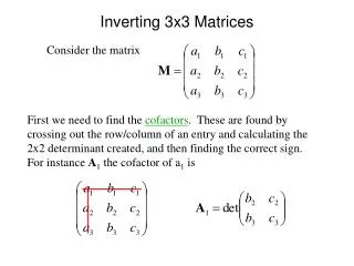
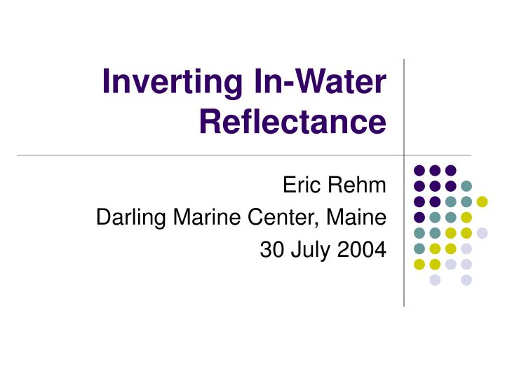
Inverting In-Water Reflectance. Eric Rehm Darling Marine Center, Maine 30 July 2004. Inverting In-Water Radiance. Estimation of the absorption and backscattering coefficients from in-water radiometric measurements Stramska, Stramski, Mitchell, Mobley Limnol. Oceanogr. 45(3), 2000, 629-641.

E N D
Inverting In-Water Reflectance Eric Rehm Darling Marine Center, Maine 30 July 2004
Inverting In-Water Radiance Estimation of the absorption and backscattering coefficients from in-water radiometric measurementsStramska, Stramski, Mitchell, MobleyLimnol. Oceanogr. 45(3), 2000, 629-641
SSA and QSSA don’t work in the water • SSA assumes single scattering near surface • QSSA assumes that “Use the formulas from SSA but treat bf as no scattering at all.
Stramska, et al. Approach • Empirical Model for estimating KE, a, bb • Requires Lu,(z,l) Eu(z,l), and Ed(z,l) • Work focuses on blue (400-490nm) and green (500-560 nm) • Numerous Hydrolight simulations • Runs with IOPs that covaried with [Chl] • Runs with independent IOPS • Raman scattering, no Chl fluorescence • Field Results from CalCOFI Cruises, 1998
Conceptual Background • Irradiance Reflectance R = Eu/Ed • Just beneath water: R(z=0-)= f *bb/a • f 1/m0where m0=cos(q) • Also (Timofeeva 1979) • Radiance Reflectance RL=Lu/Ed • Just beneath the water • RL(z=0-) =(f/Q)(bb/a), where Q=(Eu/Lu) • f and Q covary f/Q less sensitive to angular distribution of light q
Conceptual Background • Assume • R(z) =Eu/Ed bb(z)/a(z) • RL(z) =Lu/Ed bb(z)/a(z), not sensitive to directional structure of light field • RL/R can be used to estimate • Many Hydrolight runs to build in-water empirical model • KE can be computed from Ed, Eu • Gershuns Law a=KE* • Again, many Hydrolight runs to build in-water empirical model of bb(z) ~ a(z)*RL(z)
Algorithm I • Profile Ed(z), Eu(z), Lu(z) • Estimate KE(z) KE(z) = –d ln(Ed(z) –Eu(z)]/dz • Derive m(z) m(Z) ~RL(z) /R(z) = Lu(z)/Eu(z) mest(lb)=0.1993+(-37.8266*RL(lb).^2+2.3338*RL(lb)+0.00056)./Rb; mest(lg)=0.080558+(-28.88966*RL(lg).^2+3.248438*RL(lg)-0.001400)./Rg • Inversion 1: Apply Gershun’s Law a(z)=KE(z)*m(z) • Inversion 2: bb ~ a(z)*RL(z) bb,est(lb)=11.3334*RL(lb).*a(lb)-0.0002; bb,est(lg)=10.8764*RL(lg).*a(lg)-0.0003; Curt’s Method 2 from LI-COR Lab! A lovely result of the Divergence Law for Irradiance
Algorithm II • Requires knowledge of attenuation coefficient c • Regress simulated m vs Lu/Eu for variety of bb/b and w0 = b/c • best=0.5*(b1+b2) b1=c – aest(underestimate) b2=bw + (bb,est-.5*bw)/0.01811 (overestimate) • Compute w0 = best/c • Retrieve based on bb/b: m2,est = mi(w0)*(Lu/Eu) + bi (w0) • As before • Use m2,est to retrieve a • Use RL and a to retrieve bb
Model Caveats • Assumes inelastic scattering and internal light sources negligible • Expect errors in bb to increase with depth and decreasing Chl. • Limit model to top 15 m of water column • Blue (400-490 nm) & Green (500-560 nm) • Used Petzold phase function for simulations • Acknowledge that further work was needed here
My Model #1 • Hydrolight Case 1 • Raman scattering only • Chlorophyll profile with 20 mg/L max at 2 m • Co-varying IOPs • 30 degree sun, 5 m/s wind, bb/b=.01 • Perhaps to high for the Case 1 waters under simulation
– model – estimate
My Model #2 • Hydrolight Case 2 • IOPs • AC-9 from 9 July 2004 Ocean Optics cruise • Cruise 2, Profile 063, ~27 m bottom • bb/b = 0.019 (bb from Wetlabs ECOVSF) • Raman scattering only • Well mixed water, [Chl] ~3.5 ug/L • 50% cloud cover
– model – estimate
Conclusions • Stramska, et al. model is highly tuned to local waters • CalCOFI Cruise • Petzold Phase Function • 15 m limitation is apparent • Requires 3 expensive sensors • Absorption is most robust measurement retrieved by this approach. Why? • Look at that AOPs making up a(z)=KE(z)*m(z) : The magnitude of m(z) does not vary much; the KE attenuation coefficient is a measure of the attenuation of the light field.
Conclusions • Forward Model #1 was more extreme than Stramska’s: • bb/b = 0.01 may have been too high for the Case I waters being simulated • Chlorophyll maximum (20 ug/L at 2m) resulted in deeper optical depth 2-3 m than the 15 meters of Stramska’s water. • 3-D graphics are useful for visualization of multi-spectral profile data and error analysis • Lots of work to do to theoretical and practical to advance IOP retrieval from in-water E and L.