Download
1 / 20
200 likes | 383 Views
The ABCN front end chip for ATLAS Inner Detector Upgrade. Jan Kaplon CERN for Francis Anghinolfi CERN Wladyslaw Dabrowski AGH Krakow Nandor Dressnandt University of Pennsylvania Daniel La Marra University of Geneva Mitchell Newcomer University of Pennsylvania

E N D
The ABCN front end chip for ATLAS Inner Detector Upgrade Jan Kaplon CERN for Francis Anghinolfi CERN Wladyslaw Dabrowski AGH Krakow Nandor Dressnandt University of Pennsylvania Daniel La Marra University of Geneva Mitchell Newcomer University of Pennsylvania Pernecker Sebastien University of Geneva Poltorak Karolina CERN Swientek Krzysztof AGH Krakow Topical Workshop on Electronics for Particle Physics Naxos, September 15-19, 2008
Outline • ABCN design in CMOS 0.25um – a testing vehicle for programs on developments of sensor and modules for the upgrade of ATLAS SCT for SLHC • Specifications • Architecture • Analogue performance • Compatibility with the alternative power distribution schemes • Readout protocol • Forecast for power consumption vs. noise performance of CMOS front end in more advanced processes Topical Workshop on Electronics for Particle Physics Naxos, September 15-19, 2008
ABCN specifications Front end chip for ATLAS SCT upgrade module program • 250nm CMOS IBM technology • Radiation tolerance • TID All NMOS transistors in enclosed geometry • SEU all configuration registers and fast command decoder with triplicated vote logic and correction (SEU event readout via STATUS register) • ATLAS binary architecture; 128 channels of preamplifier/shaper/comparator with two memory banks for trigger latency and derandomizer • Front end optimized for 5pF detector capacitance (short strip silicon detector) and compatible with either detector signal polarity • Shaper designed for 25ns peaking time providing 75ns double pulse resolution and comparator walk less than 15ns (compatible with 25ns BCO) • On chip shunt regulators allowing for serial powering of the modules • On chip linear voltage regulator for analogue supply (can operate with noisy supply from DC/DC converter) • Readout clock up to 80 Mbits/s Topical Workshop on Electronics for Particle Physics Naxos, September 15-19, 2008
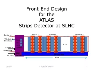
ABCN architecture • Full custom layout of front end, DACs, Calibration, power management and memory section • Synthesized layout of readout controlled and logic, command decoder, data compression and serializer Topical Workshop on Electronics for Particle Physics Naxos, September 15-19, 2008
Design methodology • Analog block • Schematic simulation, full custom layout, LVS, post-extracted simulation • Digital block • Verilog design and simulations • Synthesis with wire load model, added test scan chain • Place and route with timing verification and optimization (First Encounter) • floorplan definition • placement • clock tree synthesis (CTS) • routing • physical verification • file generation: netlist, GDS and SDF, wire load model • Verilog simulation with postP&R netlist and SDF (Standard Delay Format) Topical Workshop on Electronics for Particle Physics Naxos, September 15-19, 2008
Front End architecture • Input transistor; NMOS 320um/0.5um, nominal bias 140uA • Nominal consumption 280uA @ 2.5V (2.2V after regulator) (0.7mW / channel) • Peaking time 25ns (22ns intrinsic) • Time walk 1.25 – 10fC @ 1fC threshold ~15ns Topical Workshop on Electronics for Particle Physics Naxos, September 15-19, 2008
Calculated ENC performance • EKV model of input transistor gate capacitance • Added 0.5pF for parasitic capacitance of the bond pad and on-chip protection diodes • without effect of ballistic deficit (~10% for charge collection of 10ns) • Nominal input transistor bias; 140uA • 22ns peaking time (nominal bias and load conditions, intrinsic peaking time) • Estimated ENC for 5pF detector capacitance and 600nA leakage < 800e- Topical Workshop on Electronics for Particle Physics Naxos, September 15-19, 2008
Analogue performance of the amplifier/comparator Minimization of the power consumption in the front end; • Bias current in the first stage defined by the ENC level • Bias current in the buffer/shaper stages limited by timing performance final adjustment of the shaper filter characteristic using spice simulation of the extracted layout with all parasitic capacitances Topical Workshop on Electronics for Particle Physics Naxos, September 15-19, 2008
Linearity and dynamic range • Differential signal as seen at comparator input; • peaking time 25ns (for 10ns charge collection time), analogue gain 100mV/fC • INL for 0-6fC <3% • INL for 0-10fC <10% Topical Workshop on Electronics for Particle Physics Naxos, September 15-19, 2008
Timing performance 1 Time walk for -1.25 to –10fC @ 1fC threshold (equivalent to 89mV); <15ns Topical Workshop on Electronics for Particle Physics Naxos, September 15-19, 2008
Timing performance 2 B) A) A) Response to two, -3.5fC signals separated by 75ns B) Response to -3.5 fC signal following a -80 fC (1us distance) Topical Workshop on Electronics for Particle Physics Naxos, September 15-19, 2008
PSRR simulation of full front end (post extract with parasitics) Worst case value for 33MHz; -7dB Topical Workshop on Electronics for Particle Physics Naxos, September 15-19, 2008
On chip power management and distribution • Two optional shunt regulators • Serial voltage regulator (optional) 2.5V Vddd Vdda Shunt1 Regulator Shunt2 Regulator Voltage Regulator ABCN Analogue ABCN Digital 2.2V gndd gnda (Substrate) On/off On/off On/off Topical Workshop on Electronics for Particle Physics Naxos, September 15-19, 2008
Compatibility with serial powering scheme • Distributed shunt architecture (on chip shunt regulators connected in parallel on the module level) • Power dissipated in the shunt regulators is distributed uniformly across the hybrid • No very high current devices required • Single point of failure reduces compared to one regulator per hybrid • Hybrid design fully scalable with respect to power distribution • Sensitivity to matching (bandgap reference and error amplifier) • Two schemes are implemented in the ABCN prototype • Shunt regulator in each ABCN chip with self adjusting voltage reference (feedback by means of current comparators limiting shunt current to the specific value (80mA?)) • Shunt transistor in each ABCN and external control common for all chips on the module Topical Workshop on Electronics for Particle Physics Naxos, September 15-19, 2008
On chip voltage regulator • Supplies analogue part of the front end • Optimized for high rejection ratio (allowing for efficient filtering of noisy voltages as provided by shunt regulator or DC/DC converters) Serial voltage regulator specs: • output 2.2V • max. load up to 100mA (40mA nominal) • any output capacitor stable Rejection ratio 33dB at 30MHz (worst case frequency for PSRR of the front end) for 100nF decoupling capacitor (7dB without decoupling) Topical Workshop on Electronics for Particle Physics Naxos, September 15-19, 2008
Readout protocol • Storage of hit data for up to 6.4us • At reception of “L1” trigger data slice is transferred to a derandomizer buffer • at reception of a TOKEN (in Slave Mode) data is extracted, compressed and serialized out of the chip on “Data” Output • at reception of a “L1” trigger (in Master Mode) data is extracted, compressed and serialized out of the chip on “Ldo” Output. In addition a preamble, BC and L1 counts are sent as header to the data Topical Workshop on Electronics for Particle Physics Naxos, September 15-19, 2008
M Tok1 Data1 Tok2 Data2 ldo Data shift Clk BC COM Lone Readout protocol modes MC Tok1 Data1 S S E E S S S ldo Data shift Data Out ABCN ABCN ABCN ABCN ABCN ABCN ABCN ABCN Tok1 Data1 Tok1 Data1 Tok1 Data1 Tok1 Data1 Tok1 Data1 Tok1 Data1 Tok1 Data1 Tok2 Data2 Tok2 Data2 Tok2 Data2 Tok2 Data2 Tok2 Data2 Tok2 Data2 Tok2 Data2 Clk BC COM Lone Readout with a module controller (MC). Chips configured as SLAVE, END chip sends trailer to MC. Base CLK CMDin Tok2 Data2 ABCD legacy mode. One chips is set as Master. The master chip reacts to the reception of L1 signal and generates the token for adjacent chips. END chip sends trailer to Master. Topical Workshop on Electronics for Particle Physics Naxos, September 15-19, 2008
Summary • Analogue specifications, functionality, as well as new power management features makes ABCN a suitable test vehicle for SCT upgrade R&D program • ABCN represents full CMOS family front end, its radiation hardness for TID is intrinsic. The architecture of the digital circuitry and its immunity to SEE is a compromise between the requirements for the error rate and power consumption (triplicated logic etc.) • Chip is expected back from the foundry soon • It is not sure which technology will be chosen for the final front end chip for the upgraded SCT detectors. The two next slides shows the predicted numbers for ENC and power consumption for front end implemented in IBM CMOS 130nm process. Demonstrators of the front end in 130nm process planned next year. Topical Workshop on Electronics for Particle Physics Naxos, September 15-19, 2008
Expected ENC performance for IBM 130nm process Long strips Short strips Id=80uA, NMOS 200/0.3 Ifeed=300nA, Ileak=600nA Id=200uA, NMOS 500/0.3 Ifeed=700nA, Ileak=1.3uA • Improvement for 130nm process due to: • lower slope factor n; 1.45 1.25 (so gm is only 25% lower wrt BJT) • no excess noise for L>250nm (Γ=1.3 for IBM250nm) • higher transconductance; KpNMOS 300 750 uA/V Topical Workshop on Electronics for Particle Physics Naxos, September 15-19, 2008
Power estimates for 130nm versions • IBM 250nm; Bias currents in shaper and discriminator stages in the range of 6 to 8uA due to the lack of high value resistors (we use polysilicon resistors 250Ω/square) Current consumption in present shaper/discriminator ; 140uA • IBM 130nm; • 1.7k Ω /square polysilicon resistors available; • Higher transconductance and better matching smaller devices Evaluation of current in shaper/discriminator for 130nm (number from design for GTK; 5ns peaking time); 50uA Total power consumption for front end in 130nm optimized for: • Short strips; 130uA @ 1.2V (160uW/channel) • Long strips; 250uA @ 1.2V (300uW/channel) Topical Workshop on Electronics for Particle Physics Naxos, September 15-19, 2008