Download
1 / 40
400 likes | 540 Views
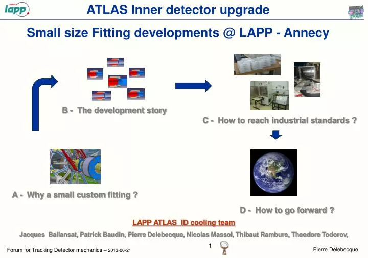
ATLAS Inner detector upgrade Small size Fitting developments @ LAPP - Annecy. B - The development story. C - How to reach industrial standards ?. A - Why a small custom fitting ?. D - How to go forward ?. LAPP ATLAS ID cooling team

E N D
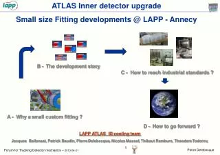
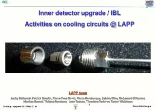
ATLAS Inner detector upgrade Small size Fitting developments @ LAPP - Annecy B - The development story C - How to reach industrial standards ? A - Why a small custom fitting ? D - How to go forward ? LAPP ATLAS ID cooling team Jacques Ballansat, Patrick Baudin, Pierre Delebecque, Nicolas Massol, Thibaut Rambure, Theodore Todorov,
1 – Introduction A verysmallfitting The fittingishere
1 – Introduction A verysmallfitting
1 – Introduction A verysmallfitting Handling is not soeasy!
1 – Introduction f 8mm A verysmallfitting – the 3 components Male Female Nut Mass=2.2g (IBL version) Tightening torque ~2N.m
1 – Introduction Fittingwelded on a titanium pipe (sample for qualification) Electron Beamwelds • Pipes outerdiameters : f 1.77 mm and f 2.27mm (IBL) • Pipes wallthickness: 130 mm (IBL) 70 mm (prototyping)
2 – Context General view of one pixel detector end
2 – Context General view of one pixel detector end (zoomed)
2 – Context Zoom on IBL end region
2 – Context Front view of the IBL end region 10
2 – Context - specifications Specifications • Small fitting, less than 8 mm : • Minimize material budget • Fit inside a limited volume • Maximum leak rate (He) : 10-5 mbar.l.s-1 @ 1bar (10-8 mbar.l.s-1 @ 20bar retained for validation) • Working temperature : mini -40 °C maxi +20 °C • Pressure (bar): • Radiation level : 1 Grad • Pipe material : Titanium grade 2 • 20 mountings / dismountings at least 10 11
3 – Why a custom fitting? • Why not using the current end-of-stave Pixel aluminium fittings for IBL ? • Problems and questions : • Leaks on the current disks, • Uncertainties on the disassembly capability • We want to use of titanium instead of aluminium • Lessons from pixel detector ? : • Need real quality management • Need qualifications • Need procedures for tests, manufacturing controls and mounting • Need tightening control The ATLAS tracker community didn’t want any custom fittings !!
3 – Why a custom fitting? ………………………………but • No industrial standard solution was complying with the IBL specifications (especially the envelope) • Swagelok: not interested in reducing the size of their connectors • Staübli : specific design proposed but very costly
3 – Why a custom fitting? So what could we do ? Custom developments was the only solution BUT…it had to be developed according to industrial standards 14
4 – Custom fitting @ LAPP : a brief history Step 0 : Copy of Luer lock pixel aluminium fitting • Same material (aluminium EN AW-6063), same design • Leak rates [2.10-7 - 10-5 ]mbar.l.s-1 @ 2bar He • Need to put strength to dismount the fittings
4 – Custom fitting @ LAPP : a brief history Step 1 : Aluminium Cone/Cone • Increasing the angle from 3.5 degrees to about 30 degrees • Changing the nut/female contact • Leak rates : no major changes comparde to Luerlock • Higher torque needed • Improvedismounting
4 – Custom fitting @ LAPP : a brief history Step 2 : Titanium grade 2 (not alloyed) Cone/Cone design 1 • Material changes Aluminium to Ti grade 2 • Design chosen from first tests on aluminium custom fittings • Tests done with samples Electron beam welded • Not sufficiently reliable (some leak tight, some not)
4 – Custom fitting @ LAPP : a brief history Step 2 : Titanium grade 2 (not alloyed) Cone/Cone design 1 Analysis of the behavior: • Extremity of the male too flexible • Gap between female and nut induces high stresses Gap
4 – Custom fitting @ LAPP : a brief history Step 2 : Titanium grade 2 (not alloyed) Cone/Cone design 2 • Change of surface contact between the nut and the female part • Not sufficiently reliable (some leak tight, some not again) • Problem of surface quality or/and hardiness suspected (material torn from the surface) • Use of electropolishing, « tribofinition » and Balinit C (carbon+tungten) coating on the cone surfaces • Did not improve the leak tightness
4 – Custom fitting @ LAPP : a brief history Step 2 : Titanium grade 5 (alloyed) Cone/Cone design 3 • Change material to Ti grade 5 (same hardness as stainless steel used for some commercial fittings) • Better results but still do not fit the specs • Some samples made of 316 L stainless steel • Good results (need at least to be tightened at 7N.m
4 – Custom fitting @ LAPP : a brief history Step 3 : Titanium grade 5 Toroid/Cone • Machining of a toroid shape instead of a cone • Improve the friction of the threads and the nut/female contact • Very good results obtained on about 50 combinations • Hybride assembly male/TA6V – Female 316L • good results obtained on few combinations
4 – Custom fitting @ LAPP : a brief history Why a sphere ? • A spherical shape is less sensitive to angular misalignment • Same conical female parts as for toroid but a different contact point Toroïde Sphere 23
4 – Custom fitting @ LAPP : a brief history Major improvement of the tightening efficiency • MOS2 (molybdenum disulphide) coating on friction surfaces (threads, back of female and nut) • 3 times more efficient compared to raw surfaces • Graphite treatment proposed by the same company is far from being so convincing • MOS2 is projected at high speed on the surface and remain attached • Rad-Hard MOS2 coating 24
5 – Test reception criteria What is a “good” fitting ? Leak rate < 10-8mbar.l.s-1 @ 20 bars He and -50°C @ 70 bars He / 20°C after a 150 bars pressure test • After 50 CO2 cool down/warm up in the range of +30°C -50°C / and 6 to 60 bars After 20 mountings/dismountings 25
6– Validation of the design – Qualification of the procedures How to obtain an “industrially qualified” fitting ? • We are able to manage the R&D phases • Industrial validation and qualification must be carried out according to specific rules/standards Experts (quality management and leak tightness) were asked to audit our project and give advice to define and implement the industrialisation and qualification procedures Production operations (machining, geometrical and dimensional controls, coating, marking) are made by industrial companies 26
6– Validation of the design – Qualification of the procedures • Main rules for an “industrially qualified” fitting • A plan must be defined and written to make sure all aspects are considered. This plan has to be checked and validated by an external authority. • Quality control is different from quality management : defining controls is not enough to unsure a good quality product • Tests devices and procedures must be first themselves qualified to be used for tests operations. Devices must be periodically controlled to check their capabilities. • International standards should be used. They can be adapted to the specific context but it has to be validated. • Parameters ( qualification and production) must be strictly recorded and managed. Any detail must be discussed and formalised with subcontractors. All “strategic” elements must be marked and their life must be tracked. • The requirement levels must be adapted in order to be efficient. 27
6– Validation of the design – Qualification of the procedures Main technical parameters related to fitting quality Material characteristics – hardness > Careful with the thermal treatments Cone and sphere surface quality and geometry-> machining / control Tightening must be carefully managed Pollution and damages-> at any step of operations (cleaning and protection procedures) 28
6 – Final validation and qualification – main tests/ Helium leak test Helium leak test P 150 He 30 t 20 T 6 1 2 3 4 5 20 t -50 29
7– Final validation and qualification – main tests/ Helium leak test • Helium leak test : • 8 samples tested together (9 sphere/cone junctions, 16 weldings) • 2013-06-17 • 32/50 samples tested • 31/32 validated 30
7– Final validation and qualification – main tests/ Helium leak test • CO2 cycling: • 50 pressure/ temp cycles • Samples are leak tested before and after cycling • Temperature are between 20°C and -40°C • Pressures are between 60 bars and 10 bars 2012-06-17 • 15/50 samples tested • 15/15 validated 31
7– Final validation and qualification – other tests • Break test : find the ultimate pressure • Pressure cycle tests : 1 million pressure cycle tests @ 100 bars (done =>leak test to be performed) • LN2 shock test • Repair test : "Repair test : damage a fitting by scratching to create a big leak, repair with glue • Frost test : cool down of a wet fitting • 20 mountings / dismountings test Repair test Break test Multi mountingsdismountings test 32
8– Status - Summary Programme • About 300 fittings produced for validation/qualification and production • 200 EB weldings • All the elements are marked and well protected • 10 different types of tests Industrial production from “INSTRUVIDE” IBL status • Qualification in progress • First cooling lines part (detector side - PP0 to PP1) to be delivered beginning of july • Second cooling lines part (PP1 to manifold) to be delivered end of 2013 • Installation in the pit spring 2014 33
9– New and further developments Male Ceramic Ti pipe New developments • Male fitting and electrical isolator brazed together • Passed the standard leak test (even at 150 bar pressure) • Too fragile for IBL (ceramic too thin) 34
10 – Conclusions A small fitting for LHC tracking detectors was successfully designed and produced Perspectives • Qualification according to industrial standards almost complete • Fitting exists in 8mm OD (IBL) and 10mm OD • Any pipe diameter below ~3mm can be used • Any pipe wall thickness below ~300 microns can be used (70 microns- ID 1.2mmpipe prototype under test) • Hybrid Titanium/stainless steel is possible (first tests are OK) • Integrated ceramic electrical break promising 36
9– Further developments Thank you 37
9– Further developments Backup slides 38
New titanium sealed fitting Nominal torque : 30 N.m (canprobablybereduced) All elements are made of Titanium M14 thread Seal 39
6– Validation of the design – Qualification of the procedures Tightening issues • Torque applied on the nut can be different from the set value Torque limitation center Torque application center Additionnal torque Strengh 40 Use thisinstead