Download
1 / 31
340 likes | 800 Views
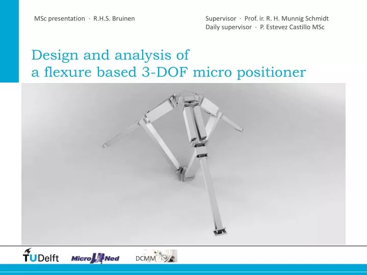
MSc presentation · R.H.S. Bruinen. Supervisor · Prof . ir . R. H. Munnig Schmidt Daily supervisor · P . Estevez Castillo MSc. Design and analysis of a flexure based 3-DOF micro positioner. Content. Introduction Conceptual design Stiffness analysis Results and conclusions.

E N D
MSc presentation · R.H.S. Bruinen Supervisor · Prof. ir. R. H. Munnig Schmidt Daily supervisor · P. Estevez Castillo MSc Design and analysis ofa flexure based 3-DOF micro positioner
Content • Introduction • Conceptual design • Stiffnessanalysis • Results and conclusions
Introduction / Application Sources: apple.com, shavers.co.uk, delfly.nl
Introduction / Haptic teleoperation Gripper User Command Haptic interface Micropositioner robot Force & vision feedback Sources: micropositioners.net, mekabot.com
Introduction / My project Specifications • Workspace 20x20x20mm • MIM (minimum incremental motion) 0,2µm • Naturalfrequency > 100Hz • Actuator forces < 1N • Velocity 0.1 m/s • Acceleration 1.5 m/s2 • … Allow3D translations, constrainrotations Micropositioner robot Source: micropositioners.net
Conceptual design / Serialor parallel Low moving mass High stiffness Small workspace Serial Parallel Sources: xyz-stage.com, pi.com
Conceptual design / Parallel mechanisms Adept Quattro Tripteron Sources: robot.gmc.ulaval.ca, motionsystemdesign.com
Conceptual design / Bearingsorflexures No dry friction Short range Bearings Flexures Sources: rchellevoet.nl, flexpivots.com
Conceptual design / Architecture Mechanism Legs Joints Beams 1 DOF 2 DOF 3 DOF Sources: kxcad.net,hephaist.co.jp
Conceptual design / Architecture Design optionsfromliterature e.g. Jin and Zhao “New kinematic structures for 2-, 3-, 4-, and 5-DOF parallel manipulator designs” Examples: 1 DOF joints High stiffness Selected: Modified Delta Cartesianmechanism U* design Source: Jin and Zhao “New kinematic structures…”, Gosselin “Compact dynamic models…”
Conceptual design / Geometry • Main design variables • Upper leg angle • Lower leg angle • Line of actuation 90° 90° in line with upper leg
Conceptual design / Joints • Flexure requirements • Low pivot stiffness Large workspace • High off-axis stiffness High resonances & precision Intersecting cross Notch 3-leaf
Stiffness analysis / Introduction Stiffness • Dimensioning • Mechanism size • Joint length, width and thickness • Mechanism performance • Workspace • MIM • Resonances F Stick-slip Case 1: Actuation force Case 2: Interaction force
Stiffness analysis / Introduction Stiffness • Dimensioning • Mechanism size • Joint length, width and thickness • Mechanism performance • Workspace • Resonances • MIM Existing literature Howell and Midha “A Method for the Design of Compliant Mechanisms With Small-Length Flexural Pivots” - 1 DOF joint - No parallel mechanisms Pham and Chen “Stiffness modeling of flexure parallel mechanism” - Theoretical approach
Stiffness analysis / Introduction Stiffness • Dimensioning • Mechanism size • Joint length, width and thickness • Mechanism performance • Workspace • Resonances • MIM Stiffness analysis Joints Legs Mechanism
Stiffness analysis / Joints Leaf Joint Bending: Stiffness around pivot axis Stiffness around off-axis Compression:
Stiffness analysis / Legs Example: Translation, X direction θ= M·Cp = F·ll·Cp Cp = joint compliance around pivot axis Δx = θ·ll = Fx·ll2·Cp Case 1: Actuation force Case 2: Interaction force
Stiffnessanalysis / Mechanism Case 1: Actuation force Case 2: Interaction force
Stiffnessanalysis / Mechanismtransformation Transform to horizontal-verticalcoordinate system withEulerrotations
Stiffnessanalysis / Dimensioning Stiffness • Mechanism size 16cm • Joint length 8mm, width 10mm and thickness 0.15mm • Dimensioning • Mechanism size • Joint length, width and thickness • Mechanism performance • Workspace • Resonances • Stick-slip 18x18x18 mm3 240 Hz 75 nm 20x20x20 mm3 100 Hz 200 nm - ++ ++ Stiffness analysis Joints Legs Mechanism
Results • Designed a flexurebased 3 DOF micropositioner • Developedstiffnessanalysismethodforflexure parallel mechanisms • ‘Second International Symposium onCompliantMechanisms’ • Submitted a paper • Created3D print • Presentation and demonstration
Conclusions • The stiffnessanalysis • Addition to existingliterature • Tool for the design of flexure parallel mechanisms • More insightinto the mechanism • The final design • High precision performance with a largeworkspace • Use in industryor research
Design and analysis ofa flexure based 3-DOF micro positioner
Conceptual design / Actuators and sensors • Selected actuator: Lorentz motor • No friction, no backlash • No added stiffness in system • Selected sensor: optical encoder • Sufficient range and resolution • Affordable
Stiffness analysis / Legs Example: Translation, X direction M=Fx·ll θ=M·Cp Δx2 = θ1·ll Δx3 = Fx·ll2·Cp CxI = ll2·Cp Case I
Stiffnessanalysis / Mechanism performance Workspace Stick-slip Resonances