Download
1 / 20
580 likes | 1.74k Views
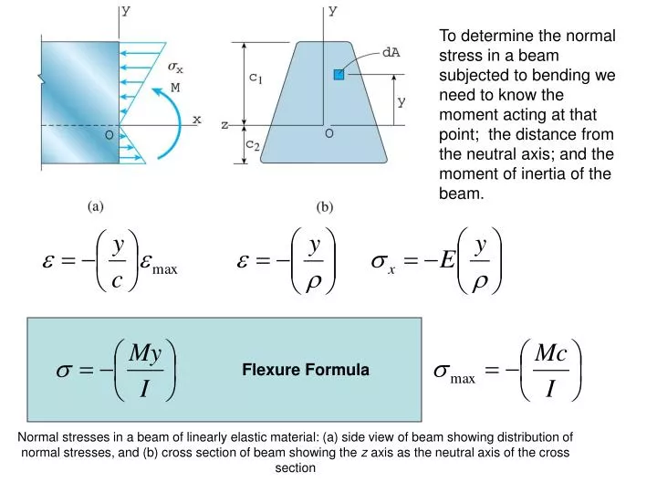
Normal stresses in a beam of linearly elastic material: (a) side view of beam showing distribution of normal stresses, and (b) cross section of beam showing the z axis as the neutral axis of the cross section.

E N D
Normal stresses in a beam of linearly elastic material: (a) side view of beam showing distribution of normal stresses, and (b) cross section of beam showing the z axis as the neutral axis of the cross section To determine the normal stress in a beam subjected to bending we need to know the moment acting at that point; the distance from the neutral axis; and the moment of inertia of the beam. Flexure Formula
Positive curvature results from positive applied moments. For positive curvature compression occurs at the top surface. The beams shown have non-symmetric cross-sections and the neutral axis is therefore not at the center.
Taking moments about the neutral z-axis (for each small slice the force is stress x area and the distance from the z-axis is y) Remember
Doubly symmetric cross-sectional shapesIf a beam is doubly symmetric (i.e. symmetric in the z and y directions, the neutral axis will be at the center of the beam. Where S=section modulus and is a geometric factor. For beam design we can calculate the required section modulus and then select.
For the beam shown determine the maximum tensile and compressive stresses in the beam. • Calculate the maximum +ve and –ve moments • Need to draw shear and moment diagrams • Mpos=2.025kN.m Mneg=-3.6 kN.m • 2) Find neutral axis
3) Calculate the maximum +ve and –ve stresses there are four combinations Mpos c1; Mpos c2; Mneg c1; Mneg c2 Tensile Compressive
A simple beam of span length 21 ft must support a uniform load q=2000lb/ft as shown. Neglecting the weight of the beam select a structural beam of wide flange shape to support the loads.1) Determine MmaxDraw shear diagram Calculate M2) Calculate required section modulus Calculate or look up max stress3) Select a beam W12x50 S=64.7 X1=9430 ft Mmax=88,920 lb-ft Smin=Mmax/allow=59.3in3 Design of Beams
A cantilever beam AB of length L is being designed to support a concentrated load at the free end . The cross-section is rectangular. Calculate the height as a function of distance so that the beam is fully stressed. I.e. at every point =allow