Download
1 / 20
210 likes | 457 Views
A Delaunay Triangulation Architecture Supporting Churn and User Mobility in MMVEs. Mohsen Ghaffari, Behnoosh Hariri and Shervin Shirmohammadi Advanced Communications Research Institute(ACRI), Sharif University of Technology, Tehran, Iran .

E N D
A Delaunay Triangulation Architecture Supporting Churn and User Mobility in MMVEs Mohsen Ghaffari, Behnoosh Hariri and Shervin Shirmohammadi Advanced Communications Research Institute(ACRI), Sharif University of Technology, Tehran, Iran. Distributed Collaborative Virtual Environment Research Lab., University of Ottawa, Ottawa, Canada.
MMVEs and their requirements • Virtual worlds where a large number of users distributed all over the Internet can interact with each other in real time. • MMVEs must deal with the real-time update message exchange. • The large number of users highly motivates the use of distributed architectures where there is no central switching point for the updates.
Geometric routing • Aimed to send an update message to a specific coordinate in space, as opposed to sending it to a specific IP address. • The use of IP routing would require a node to make a location query to know who is located in its area of effect. • Efficiency of geometrical routing is closely related to the structure of the overlay network. • The overlay must be a highly dynamic as users frequently join, leave or change their locations. Send to location Virtual Environment Geometric Routing Overlay
Greedy Routing - Motivation • Due the highly dynamic characteristics MMVEs, it is almost impossible for the nodes to gather information of all possible locations and available links. • Therefore, the use of an online routing method is highly motivated where topology data centralization is not required. • Greedy routing • Among the simplest and most common routing algorithms that can be used in geometrical routing context. • Tries to select the closest available node as the next hop for the packets. • Is only supported over a specific family of overlay graphs
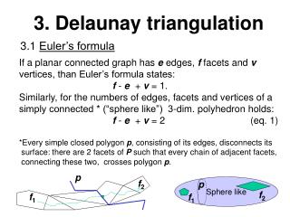
Definitions - Voronoi Cell and Delaunay Triangulation • Voronoi Cells • Partition the plane. • Voronoi Cell of each point vi, VC(vi), is defined as the set of all points in the plane that are closer to vi than any other point. • No Overlap • Delaunay Triangulation • Graph formed from Voronoi Cells • Delaunay Triangulation is a graph G=(V, E) wheree=(vi, vj) is in E, iff VC(vi) and VC(vj) has a side in common. Voronoi Cells Delaunay Triangulation Graph Points on a plane
Definitions - Vertex Region • Consider a graph G = (V, E). For each vertex vi, we define the Vertex Region of vi in graph G, VRG(vi), as the set of all points in the plane that are closer to vi than to any of its neighbors in G. Arbitrary Graph Set of Nodes Vertex Region
Necessities of Overlay to support Greedy Routing • Theorem 1: Graph G = (V, E) in the Euclidian plane supports greedy routing iff for every node vi in V, VRG(vi) = VC(vi). • Theorem 2:Graph G = (V, E) in the Euclidian plane supports greedy routing iff for all vi, vj in V, VRG(vi) ∩VRG(vj) = ф. • Therefore, in order to support greedy routing, it suffices to connect each pair of nodes that their VRG’s have a nonempty intersection.
Motivation of RED-BLACK ARCHITECTURE • Nodes are usually in movement and they use location update messages for announcing their new locations to the other nodes. • BUT: destination nodes may also be in motion. • The challenge for the fully distributed topology update is the lack of any fixed points that can be used as landmarks to help the nodes in topology reconstruction after any movement.
The idea of RED-BLACK ARCHITECTURE • To deal with this problem/, we divide the nodes into two sets called Red and Black. • Nodes of each set send their update messages in one of the update phases. • Therefore each set is able to use the other set as its landmark in order to update itself.
Outline of the RED-BLACK ARCHITECTURE Phase Shifted Update Cycles • This architecture has two graphs in the background, red and black. • Red and black graphs have separate updated phases and always will support greedy routing. • This architecture also has a main graph on all of the nodes which would be the main overlay of the network. • The red and black graphs are used only as a substrate to retain the main graph. Update Cycle = T seconds Red: 0, T, 2T, 3T, 4T… 3T/2, Black: T/2, 5T/2, 7T/2, 9T/2…
Updating Red Graph Using the Black Graph Since there is no single point where all of information required for checking overlaps is located, we need a distributed method. To update the red graph to support greedy routing, the idea is to find the overlaps between vertex regions and connect relevant nodes to eliminate this overlaps . The point is if we connect two nodes, the intersection of their vertex regions would be empty. • RED UPDATE CYCLE: • 1)Red positions are updated in Red graph • Red connections remain • Black graph does not change • 2) Red nodes notify Black nodes • 3) Black nodes check Red graph correctness • 4) Main graph is updated
Updating Red Graph Using the Black Graph • To maintain greedy routing support in the red graph, the black nodes would be used as the reliable substrate of this distributed method. • The specifications of each VRR(vi) (the vertex region of vi in the red graph) will be sent to all the black nodes whose their VRB (the vertex region in the black graph) has a nonempty intersection with this VRR.
How to disseminate specifications of VRR(vi) • Each red node reminds the nearest black node of itself (named its black owner). • During the red update period, each red node sends the specifications of its red vertex region to its previous black owner and asks the black owner to return the message to itself using the black graph. • Since the black graph supports greedy routing, this packet will get to the red node’s new black owner.
How to disseminate specifications of VRR(vi) • Upon the reception of every new VRRspecification by a black node, the black node propagates the received VRRspecification to every black neighbor in the black graph whose VRB’s common side (or point) has a nonempty intersection with the VRRencapsulated in the message. • Theorem 3: With the above method, the message encapsulating VRR(vi) will be received by a black node iff the black vertex region of it has a nonempty intersection with VRR(vi).
Vertex Region Overlap Detection • If there is an overlap, the overlap will be in the black vertex region of one node, therefore this black node will receive the specifications of both of overlapping vertex regions and will find out the overlap.
Improvement of the Update Algorithm • Before propagating the messages in black nodes, every black node checks for the red VRR-s overlap and updates the message contents. Then the message will be broadcasted to neighbors which their black vertex region have common point with this updated VRR.
Update of the main graph • Upon the reception of a new VRR(vi) in each black node, the black node checks the vi as a candidate of neighborhood in the main graph. • If candidateship is granted, it sends a neighborhood request message to viincluding its own location. • The black node also re-computes its main graph in the presence of vi as a new neighbor.
Simulation Results • It can be seen that delightfully, the number of nodes in the area has a slight effect on the termination time of the proposed method
Simulation Results • Number of messages sent in the resumption algorithm has an approximately linear relation with the number of nodes and thus, average number of messages transmitted by every node is almost constant
Fin. Thank You.