Download
1 / 17
341 likes | 947 Views
Orthorectification and Triangulation. Orthorectification and Triangulation. Topics to discuss Orthophotos what are they? How are they produced? Forward and Backward Projection True Ortho. Orthorectification and Triangulation. Orthophotos What is Orthorectification??

E N D
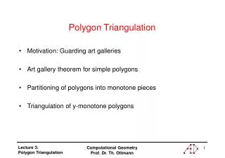
Orthorectification and Triangulation • Topics to discuss • Orthophotos • what are they? • How are they produced? • Forward and Backward Projection • True Ortho
Orthorectification and Triangulation Orthophotos What is Orthorectification?? - The process of removing geometric error: - Camera orientation - Systematic error associated with camera/lens distortion etc. - Relief displacement - Earth curvature
Orthorectification and Triangulation Generated by an elevation model (DEM) and an aerial photo. The elevation model can be generated by the same stereoscopic photographs, so no other source of data is needed. Shows photographic detail without errors caused by tilt and relief displacement. Orthographic projection rather than central perspective properties. An orthophoto combines the advantages of a map (constant scale, orthographic projection) and those of a photo (photographic realism and level of detail).
Orthorectification and Triangulation Producing and Orthophoto Orthophotos are produced by first obtaining or generating a DEM of the area. This elevation information is then used to remove the elevation effects (the relief displacement) from the perspective image by reprojection. There are two basic approaches to generating orthophotos; forward projection and backward projection.
Orthorectification and Triangulation Forward Projection - Pixels in the source image are projected onto the DEM and their object space coordinates (XYZ) are determined; the object space points are then projected orthographically onto the orthoimage plane (Z=0). Since the spaces between the points projected into the orthoimage vary due to the terrain variation and perspective effects, the final orthoimage pixels must be determined by interpolating between the projected points.
Orthorectification and Triangulation Backward Projection - The object space coordinates (X,Y) corresponding to each pixel in the final orthoimage are calculated. The elevation (Z) for each of these XY points are then obtained from the DEM, and the resulting XYZ points are projected into the source image to find out from which image point (x’,y’) to obtain the grey value for the orthoimage pixel. Since the projected object space coordinates will not fall exactly at pixel centers in the image, interpolation must be done in the source image.
Orthorectification and Triangulation True Ortho - Orthophotos that only rely on DEM/DTM data will only take away the relief displacement effect from the terrain elevation, all other protruding objects (trees, buildings etc.) will still show their radial displacement in the final orthophoto. To reduce these effects too, and achieve a so called ”True Orthophoto”, there is need for DSM data.
Orthorectification and Triangulation True Ortho – True orthos often have problem with blind spots and missing data.
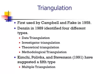
Orthorectification and Triangulation Triangulation – In trigonometry and geometry, triangulation is the process of determining the location of a point by measuring angles to it from known points at either end of a fixed baseline, rather than measuring distances to the point directly. The point can then be fixed as the third point of a triangle with one known side and two known angles. Triangulation can also refer to the accurate surveying of systems of very large triangles, called triangulation networks. Triangulation is a way of determining something's location using the locations of other things. It is commonly used by geologists to find the locations of Earthquakes, and is also used to determine spacecraft location. There are several ways to use triangulation to figure out location. Here's how it works. Triangulation is the principle used by photogrammetric technicians to produce 3-dimensional point measurements. By mathematically intersecting converging lines in space, the precise location of the point can be determined. If the XYZ coordinates of the points on the object are known, we can compute orientation.
Orthorectification and Triangulation Triangulation Example - A set of 4 QuickBird images of the Phoenix, Arizona area, with support data and ground control points were provided by DigitalGlobe for purposes of validating the RemoteView triangulation with the rigorous QuickBird sensor model. The block consists of 2 images from one pass and 2 images from another pass. Within each pass, the initial relative orientation of the images is quite good, within about 10 meters. Across the paths however, there is a large misalignment of nearly 700 meters. Figure 4 shows one of the cross-track stereo pairs, before adjustment.
QuickBird Stereo Pair before adjustment. Note the large displacement in the north-south direction as seen in the major highway. Figure 5 shows the same stereo pair after block adjustment. For this adjustment, no ground control points were used. 24 tiepoints were generated automatically in approximately 1 minute. The relatively large amount of time required to generate tiepoints reflects the poor initial Relative Orientation of the images.
Orthorectification and Triangulation Before and after block adjustment for the entire 4-image block data is shown in Table 2. For this adjustment, 1 GCP and 32 tiepoints were used. Two GCPs were used as tiepoints to compute the RMS errors. The adjustment required 4 iterations and completed in under 15 seconds, computing 24 sensor parameters and the coordinates of all tiepoints and checkpoints.
Orthorectification and Triangulation Sources for further study: http://web.pdx.edu/~jduh/courses/geog493f08/Students/VTeeters.pdf http://www.mundi.net/locus/locus_008/ http://www.geodetic.com/Whatis.htm http://geospatial.overwatch.com/White_Papers_PDF/Multi%20Sensor.pdf http://www.cas.sc.edu/geog/rslab/index.html - Good site with exercises created by J. Jensen, USC http://depts.washington.edu/rsgal/ http://seamless.usgs.gov/index.php http://www.asprs.org/publications/pers/98journal/april/1998_apr_329-333.pdf