Download
1 / 28
320 likes | 561 Views
FPGA Configuration. Introduction. Configuration Data Source. FPGA. Control Logic (optional). What is configuration? Process for loading data into the FPGA. Introduction. When does configuration happen? On power-up On demand Why do FPGAs need to be configured?

E N D
Introduction Configuration Data Source FPGA Control Logic (optional) • What is configuration? • Process for loading data into the FPGA
Introduction • When does configuration happen? • On power-up • On demand • Why do FPGAs need to be configured? • FPGA configuration memory is volatile • What do I need to know about FPGA configuration? • What happens during configuration • How to set up various configuration modes and daisy-chains • How to troubleshoot problems
FPGA Configuration Process • In order to understand the configuration process, you need to know a little about: • Configuration modes • Configuration pins
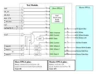
Configuration Modes • Configuration modes define the specifics of how the FPGA will interact with: • The data source • External control logic (if any) • Many configuration modes to choose from • Serial modes (Master and Slave) • SelectMAP mode (Slave Parallel) • Boundary scan mode (Slave) - always available • Other Xilinx FPGA families have more configuration modes
Configuration Modes Note: • Configuration pins (M0, M1, M2))
Configuration Modes:Serial Modes • Data is loaded 1 bit per CCLK • Master serial • FPGA drives configuration clock (CCLK) • FPGA provides all control logic • Slave serial • External control logic required to generate CCLK • Microprocessor • Xilinx serial download cable • Another FPGA CCLK Serial Data FPGA Data Serial Data FPGA Data CCLK Control Logic
Configuration Modes:SelectMAP Mode • CCLK is driven by external logic • Data is loaded 1 byte per CCLK Byte-Wide Data FPGA Data Control Signals CCLK Control Logic
Configuration Modes:Boundary Scan Mode • External control logic required • Control signals and data are presented on the boundary scan pins (TDI, TMS, TCK) • Data is loaded 1 bit per TCK • Always available (independently on M0,M1,M2) Serial Data FPGA Data Control Signals Control Logic
Configuration Pins • Specific pins on the FPGA are used during configuration • Some pins act differently depending on configuration mode • Example: CCLK is an output in some modes and an input in others • Some pins are only used in specific configuration modes • Example: CCLK is not used for Boundary Scan mode
Configuration Pin Descriptions • Mode Pins (M0, M1, M2) • Input pins that select which configuration mode is being used • PROGRAM • Active low input that initiates configuration • CCLK (Configuration Clock) • Input or output, depending on configuration mode • Frequency up to 10MHz (see Data Book for your device family) • DIN • Serial input for configuration data
Configuration Pin Descriptions • DOUT • Output to next device in a daisy-chain • Used in daisy-chains only • INIT • Open-drain bi-directional pin • Error and Power Stabilization Flag • DONE • Open-drain bi-directional pin • Indicates completion of configuration process • Other pins are used for specific configuration modes • (i.e. JTAG Pins)
Configuration Process • Four major phases in the process: • Configuration memory clear • Initialization • Load configuration data • Start-up
Configuration Process Configuration Memory Clear Phase • 2 Way to configure (power up - Program) • Non-configuration I/O pins are disabled with optional pull-up resistors • INIT and DONE pins are driven low • FPGA memory is cleared • PROGRAM is checked after each memory pass • Proceed to initialization Initialization
Configuration Process:Initialization Phase INIT High? Sample Mode Pins Release INIT • INIT pin is released • INIT may be held low externally to delay configuration • Mode pins are sampled • Appropriate configuration pins become active • Proceed to load configuration data Configuration Memory Clear No Yes Load Configuration Data
Configuration Process:Load Configuration Data Phase CRC Correct? Load Data Frames Pull INIT Low • FPGA starts receiving data • CRC is checked during the data frames transmission • If incorrect value received, INIT is driven low and rest of data is ignored • If the CRC checks pass, proceed to start-up Initialization No Yes Start-Up
Configuration Process:Start-up Phase Activate I/O Pins Release DONE Release GWE Release GSR • Transition phase from configuration to normal operation • Order of events is user programmable • Accessed through software options • Default sequence is: • DONE pin is released • All I/O pins become active • Global write enable released • Global reset released • FPGA is operational Load Configuration Data FPGA is Operational
Configuration Process:Start-up Phase • Default sequence is: • DONE pin is released • All I/O pins become active • Global write enable released • Global reset released • Another useful sequence is “Sync to DONE” • Useful for multiple FPGA configuration (Daisy chain) • Configuration option
Master Serial Mode • All mode pins tied low • FPGA drives CCLK as an output • Data stream loaded 1 bit at a time • Use when data stream is stored in a serial PROM
Slave Serial Mode • All mode pins tied high • FPGA receives CCLK as an input • Data stream loaded 1 bit at a time • Use with the xilinx serial download cable
What Is a Daisy-Chain? • Multiple FPGAs connected in series for configuration • Allows configuration of many devices from a single data source • Minimal board traces • First device in the chain can be in master serial or slave serial mode • All other devices must be in slave serial mode
Daisy-Chain Question • How do you think these FPGAs could be connected to form a Daisy-chain?
Daisy-Chain Answer • Connect all PROGRAM, CCLK and DONE pins together • Connect each DOUT to the DIN of next device • Recommend connecting INIT pins, but not required
Creating a Daisy-Chain • Connect PROGRAM pins • Required so that all FPGAs will reprogram together • Connect CCLK pins • Required so that all FPGAs are synchronized with each other and with the configuration data • Connect DONE pins • Required so that all FPGAs start-up together • Connect each DOUT to the DIN of next device • Required to allow each FPGA to receive configuration data • Connect INIT pins • Recommended to create a single error flag, but not required
How a Daisy-Chain Works • First FPGA in the chain is configured first • Keeps DOUT high until its configuration memory is full • Then data is passed to the next device in the chain • Start-up sequence occurs after all devices are configured • FPGA devices pause after internally releasing DONE, and continue when DONE externally goes high
Review Questions • Which phase of the configuration process takes the most time? • What is the main difference between the master serial and slave serial configuration modes?
Answers • Which phase of the configuration process takes the most time? • The load configuration data phase takes the bulk of the configuration time • What is the main difference between the master serial and slave serial configuration modes? • CCLK is an output in master serial, input in slave serial
Summary • Field programmable devices are configured on power-up from an external data source • The phases of the configuration process are: • Configuration memory clear • Initialization • Load configuration data • Start-up • Master serial and slave serial are the simplest configuration modes