Download
1 / 17
230 likes | 833 Views
MATERIALS SCIENCE & ENGINEERING . Part of . A Learner’s Guide. AN INTRODUCTORY E-BOOK. Anandh Subramaniam & Kantesh Balani Materials Science and Engineering (MSE) Indian Institute of Technology, Kanpur- 208016 Email: anandh@iitk.ac.in, URL: home.iitk.ac.in/~anandh.

E N D
MATERIALS SCIENCE & ENGINEERING Part of A Learner’s Guide AN INTRODUCTORY E-BOOK Anandh Subramaniam & Kantesh Balani Materials Science and Engineering (MSE) Indian Institute of Technology, Kanpur- 208016 Email:anandh@iitk.ac.in, URL:home.iitk.ac.in/~anandh http://home.iitk.ac.in/~anandh/E-book.htm DISLOCATION STRESS FIELDS • Dislocation stress fields → infinite body • Dislocation stress fields → finite body • Image forces • Interaction between dislocations Advanced reading (comprehensive) Theory of DislocationsJ. P. Hirth and J. Lothe McGraw-Hill, New York (1968)
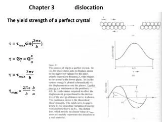
Stress fields of dislocations Edge dislocation • We start with the dislocation elastic stress fields in an infinite body • The core region is ignored in these equations (which hence have a singularity at x = 0, y = 0)(Core being the region where the linear theory of elasticity fails) • Obviously a real material cannot bear such ‘singular’ stresses stress fields The material is considered isotropic (two elastic constants only- E & or G & ) → in reality crystals are anisotropic w.r.t to the elastic properties Strain fields Displacement fields Plots in the coming slides
Note that the region near the dislocation has stresses of the order of GPa Position of the Dislocation line into the plane More about this in the next slide yy xx 286 Å Stress values in GPa 286 Å Material properties used in the plots are in the last slide
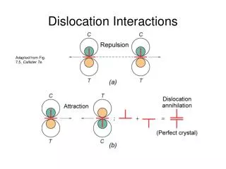
xx Left-right mirror symmetry Tensile Compressive Up down ‘inversion’ symmetry(i.e. compression goes to tension)
Stress fields in a finite cylindrical body • In an infinite body the xx stresses in one half-space maintain a constant sign (remain tensile or compressive) → in a finite body this situation is altered. • We consider here stresses in a finite cylindrical body. • The core region is again ignored in the equations. • The material is considered isotropic (two elastic constants only). Finite cylindrical body The results of edge dislocation in infinite homogeneous media are obtained by letting r2 → ∞ Plots in the coming slides
yy Polar coordinates Cartesian coordinates Stress fields in a finite cylindrical body xx 286 Å Stress values in GPa 286 Å
Like the infinite body the symmetries are maintained.But, half-space does not remain fully compressive or tensile Compressive stress Left-right mirror symmetry Not fully tensile xx Tensile stress Up down ‘inversion’ symmetry(i.e. compression goes to tension)
Stress fields of dislocations Screw dislocation • The screw dislocation is associated with shear stresses only Cartesian coordinates Polar coordinates Plots in the next slide
yz xz 572 Å Stress values in GPa 572 Å
Understanding stress fields of mixed dislocations: an analogy • For a mixed dislocation how to draw an effective “fraction” of an ‘extra half-plane’? • For a mixed dislcation how to visualize the edge and screw component?This is an important question as often the edge component is written as bCos →does this imply that the Burgers vector can be resolved (is it not a crystallographically determined constant?)
STRESS FIELD OF A EDGE DISLOCATION X – FEM SIMULATED CONTOURS FILM 28 Å SUBSTRATE b 27 Å (MPa) (x & y original grid size = b/2 = 1.92 Å)
CONCEPT OF IMAGE FORCES & STRESS FIELDS IN THE PRESENCE OF A FREE SURFACE • A dislocation near a free surface (in a semi-infinite body) experiences a force towards the free surface, which is called the image force. • The force is called an ‘image force’ as the force can be calculated assuming an negative hypothetical dislocation on the other side of the surface (figure below). A hypothetical negative dislocation is assumed to exist across the free-surface for the calculation of the force (attractive) experienced by the dislocation in the proximal presence of a free-surface
Image force can be thought of as a ‘configurational force’ → the force tending to take one configuration of a body to another configuration. • The origin of the force can be understood as follows:◘ The surface is free of tractions and the dislocation can lower its energy by positioning itself closer to the surface. ◘ The slope of the energy of the system between two adjacent positions of the dislocation gives us the image force (Fimage = Eposition 1→2 /b) • In a finite crystal each surface will contribute to an ‘image dislocation’ and the net force experienced by the dislocation will be a superposition of these ‘image forces’. An approximate formula derived using ‘image construction’ • Importance of image stresses:If the image stresses exceed the Peierls stress then the dislocation can spontaneously move in the absence of externally applied forces and can even become dislocation free!
In a finite crystal each surface will contribute to an ‘image dislocation’ and the net force experienced by the dislocation will be a superposition of these ‘image forces’. • The image force shown below is the glide component of the image force (i.e. along the slip plane, originating from the vertical surfaces) • It must be clear that no image force is experienced by a dislocation which is positioned symmetrically in the domain. Superposition of two images Glide
Similarly the climb component of the image force can be calculated (originating from the horizontal surfaces) Superposition of two images Climb
Stress fields in the presence of an edge dislocation Deformation of the free surface in the proximity of a dislocation (edge here) leads to a breakdown of the formulae for image forces seen before! Left-right mirror symmetry of the stress fields broken due to the presence of free surfaces
Material properties of Aluminium and Silicon used in the analysis