Download
1 / 26
260 likes | 287 Views
Twinning Dislocation Reactions. Deformation by Twinning. The second important mechanism by which metals deform is the process known as twinning.

E N D
Deformation by Twinning • The second important mechanism by which metals deform is the process known as twinning. • Twinning results when a portion of the crystal takes up an orientation that is related to the orientation of the rest of the untwinned lattice in a definite, symmetrical way. • The twinned portion of the crystal is a mirror image of the parent crystal. • The plane of symmetry between the two portions is called the twinning plane.
Note that the twin is visible on the polished surface because of the change in elevation produced by the deformation and because of the difference in crystallographic orientation between the deformed and unreformed regions. • It should be noted that twinning differs from slip in several specific respects. • In slip, the orientation of the crystal above and below the slip plane is the same after deformation as before, while twinning results in an orientation difference across the twin plane.
Slip is usually considered to occur in discrete multiples of the atomic spacing, while in twinning the atom movements are much less than an atomic distance. • Slip occurs on relatively widely spread planes, but in the twinned region of a crystal every atomic plane is involved in the deformation.
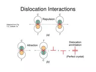
Dissociation or Combination of Dislocations • In general, a dislocation line cannot end inside of a crystal. The exception is at a node, where three or four dislocation lines meet. • At a node two dislocations with Burgers vectors b1and b2 combine to produce a resultant dislocation b3. • The vector b3 is given by the vector sum of b1 and b2 .
A dislocation with a Burgers vector equal to one lattice spacing is said to be a dislocation of unit strength. • Because of energy considerations, dislocations with strengths larger than unity are generally unstable and dissociate into two or more dislocations of lower strength.
The criterion for deciding whether or not the dissociation will occur is based on two conditions: (a) The strain energy of a dislocation, which is proportional to the square of its Burgers vector. The dissociation will occur if The reaction will not occur if (b) The vector addition (or subtraction) of the Burgers vector b must agree. (13.1a) (13.2a)
In adding burgers vectors, each of the corresponding components are added separately. • Thus • In adding or subtracting components common unit vectors must be used. • Thus must be expressed as:
A Burgers vector is specified by giving its components along the axes of the crystallographic structure cell. • Thus, the Burgers vector for slip in a cubic lattice from a cube corner to the center of one face has the components (see Figure 11-7) • The Burgers vector is , or generally written as . • The magnitude of a dislocation with Burgers vector is given as: (13.3)
Therefore, the magnitude of the Burgers vector given above is .
Example Determine whether the dislocation dissociation reaction is feasible. • Since this vector equation the x, y, and z components of the right-hand side of the equation must equal the x, y, and z components of the left side (original dislocation).
Dislocations in the Face-centered cubic lattice • Slip occurs in the fcc lattice on the {111} plane in the <110> direction. • The shortest lattice vector is (ao/2)[110], which connects an atom at a cube corner with a neighboring atom at the center of a cube face. • The Burgers vector is therefore (ao/2)[110].
However, consideration of the atomic arrangement on the {111} slip plane shows that slip will not take place so simply. • Figure 13-3 represents the atomic packing on a close-packed (111) plane. • It has already been shown (see Fig 11-4a) that the {111} planes are stacked on a sequence ABCABC….
Figure 13-3. Slip in a close-packed (111) plane in an fcc lattice
The vector defines one of the observed slip directions. • The same shear displacement as produced by b1 can be accomplished by the two-step path b2 + b3 . • The latter displacement is more energetically favorable but it causes the perfect dislocation to decompose into two partial dislocations.
The above reaction is energetically favorable since there is a decrease in strain energy proportional to the change _______________________________________________ Original dislocationProduct of reaction
Slip by this two-stage process creates a stacking fault ABCAC ABC in the stacking sequence. • As Fig. 13-4 shows, the dislocation with Burgers vector has been dissociated into two partial dislocations and . • This dislocation reaction was suggested by Heidenreich and Shockley. • Therefore this dislocation arrangement is often known as Shockley partials, since the dislocations are imperfect ones which do not produce complete lattice translations. • Figure 13-4 represents the situation looking down on (111) along .
Figure 13-4. Dissociation of a dislocation into two Shockley partial dislocations.
With the sequence ABC AC ABC, we have four planes in which the stacking is CA CA, which is exactly the stacking of HCP structure. • This structure has a higher Gibbs free energy than the equilibrium FCC structure. • This specific array of planes is called the stacking fault, and the energy associated with it determines the separation between the two partial dislocations
The repulsive force between the two partials is balanced by the attraction trying to minimize the region with the stacking fault. • The equation for the calculation of the equilibrium separation between the partial dislocations d is given as: where is the stacking-fault free energy (SFE) per unit area, (13.4) (13.5)
bp is the Burgers vector of the partial dislocation, and is the angle of the Burgers vector with the dislocation line. Table 13.1 presents the SFEs for some materials Table 13-1. SFEs and Shockley Separations of Materials
From the preceding equations, it can be seen that d is inversely proportional to . • Aluminum, which has a high SFE (166 mJ/m2), does exhibit a very small separation between partials: 1 nm. • SFE is very sensitive to composition • Addition of alloying elements in a material helps to decrease the SFE. Examples: • Brasses have SFE lower than that of Cu, • Al alloys have SFE lower than that of Al, • the addition of Al to Cu drops the SFE from 78 to 6 mJ/m2. • Figure 13-5 shows stacking faults in 302 stainless steel viewed by TEM - seen as characteristic fringe (////) pattern.
Low-SFE metals tend to exhibit a deformation substructure characterized by banded, linear arrays of dislocations. Cross-slip is more difficult, because the dislocations have to constrict in order to change slip planes. • High-SFE metals tend to exhibit dislocations arranged in tangles or cells.
Figure 13-5. Group of stacking faults in 302 stainless steel stopped at boundary on left-hand side.