Download
1 / 1
10 likes | 118 Views
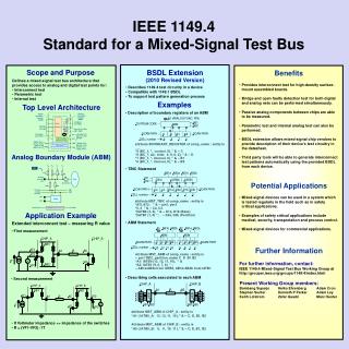
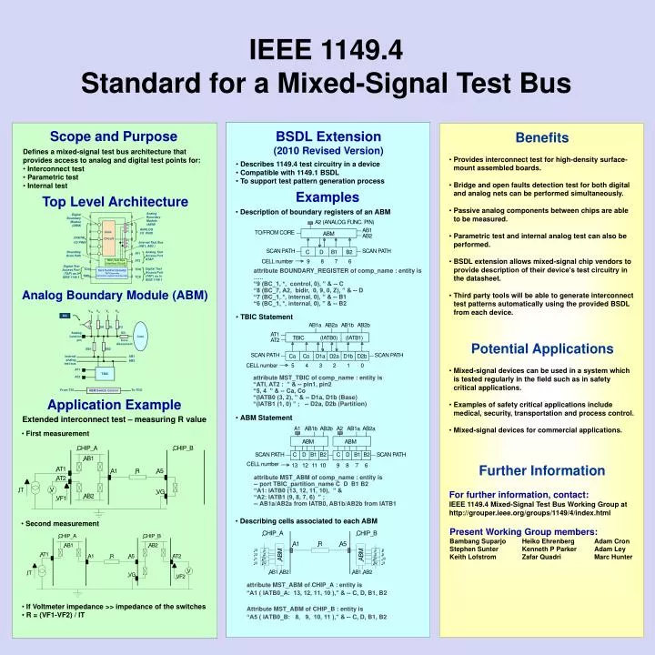
Core. Circuit. Analog Boundary Module (ABM) . Digital Boundary Module (DBM) . V H. V L. ANALOG I/O PINS. V G. DIGITAL. V H. I/O PINS. Internal Test Bus (AB1, AB2 ). V L. V G. Boundary Scan Path. Analog Test Access Port ATAP . AT1. V TH. V H. V L. V G. DS. AT2.

E N D
Core Circuit Analog Boundary Module (ABM) Digital Boundary Module (DBM) VH VL ANALOG I/O PINS VG DIGITAL VH I/O PINS Internal Test Bus (AB1, AB2 ) VL VG Boundary Scan Path Analog Test Access Port ATAP AT1 VTH VH VL VG DS AT2 TBIC (Test Bus Interface Circuit) Digital Test Access Port (TAP) as in IEEE 1149.1 - Core Digital Test Access Port (TAP ) as in IEEE 1149.1 TDI TDO + SH SL SG Test Control Circuitry TAP Controller Instruction register and decoder Analog function pin SD TMS TCK Core disconnect SB1 SB2 Internal analog test bus AB1 AB2 AT1 TBIC AT2 From TDI ABM Switch Control To TDO IEEE 1149.4 Standard for a Mixed-Signal Test Bus Scope and Purpose BSDL Extension (2010 Revised Version) Benefits • Defines a mixed-signal test bus architecture that provides access to analog and digital test points for: • Interconnect test • Parametric test • Internal test • Provides interconnect test for high-density surface-mount assembled boards. • Bridge and open faults detection test for both digital and analog nets can be performed simultaneously. • Passive analog components between chips are able to be measured. • Parametric test and internal analog test can also be performed. • BSDL extension allows mixed-signal chip vendors to provide description of their device’s test circuitry in the datasheet. • Third party tools will be able to generate interconnect test patterns automatically using the provided BSDL from each device. • Describes 1149.4 test circuitry in a device • Compatible with 1149.1 BSDL • To support test pattern generation process Examples Top Level Architecture • Description of boundary registers of an ABM attribute BOUNDARY_REGISTER of comp_name : entity is ….. “9 (BC_1, *, control, 0), ” & -- C “8 (BC_7, A2, bidir, 0, 9, 0, Z), ” & -- D “7 (BC_1, *, internal, 0), ” & -- B1 “6 (BC_1, *, internal, 0), ” & -- B2 Analog Boundary Module (ABM) • TBIC Statement Potential Applications • Mixed-signal devices can be used in a system which is tested regularly in the field such as in safety critical applications. • Examples of safety critical applications include medical, security, transportation and process control. • Mixed-signal devices for commercial applications. attribute MST_TBIC of comp_name : entity is “ATI, AT2 : ” & -- pin1, pin2 “5, 4 ” & -- Ca, Co “(IATB0 (3, 2), ” & -- D1a, D1b (Base) “(IATB1 (1, 0) ” ; -- D2a, D2b (Partition) Application Example • ABM Statement Extended interconnect test – measuring R value • First measurement Further Information attribute MST_ABM of comp_name : entity is -- port TBIC_partition_name C D B1 B2 “A1: IATB0 (13, 12, 11, 10), ” & “A2: IATB1 (9, 8, 7, 6) ” ; -- AB1a/AB2a from IATB0, AB1b/AB2b from IATB1 For further information, contact: IEEE 1149.4 Mixed-Signal Test Bus Working Group at http://grouper.ieee.org/groups/1149/4/index.html • Describing cells associated to each ABM • Second measurement Present Working Group members: BambangSuparjoHeikoEhrenberg Adam Cron Stephen SunterKenneth P Parker Adam Ley Keith LofstromZafarQuadriMarc Hunter attribute MST_ABM of CHIP_A : entity is “A1 ( IATB0_A: 13, 12, 11, 10 ),” & -- C, D, B1, B2 Attribute MST_ABM of CHIP_B : entity is “A5 ( IATB0_B: 8, 9, 10, 11 ),” & -- C, D, B1, B2 • If Voltmeter impedance >> impedance of the switches • R = (VF1-VF2) / IT