Download
1 / 27
280 likes | 450 Views
TLM example application. T. Leveling March 15, 2013. Attendees: Don Cossairt Kamran Vaziri Adam Olson Dave Peterson John Anderson Paul Czarapata Tony Leveling. Controlled beam loss location. A2B7, a bending magnet in the Accumulator ring

E N D
TLM example application T. Leveling March 15, 2013 Attendees: Don Cossairt Kamran Vaziri Adam Olson Dave Peterson John Anderson Paul Czarapata Tony Leveling
Controlled beam loss location • A2B7, a bending magnet in the Accumulator ring • First bend element following injection into Accumulator • With bend bus de-energized, all beam is lost on this magnet • Studied during 2000 shielding assessment • Measurement verified in 2011/2012 • MARS simulations to compare with measurements
MARS simulations didn’t match measurementspossible cause – unknown soil density
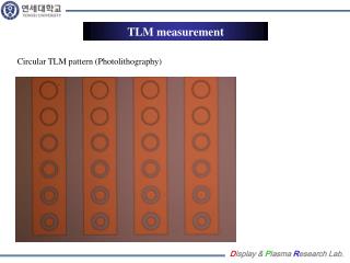
TLM measurement unit • Based upon months of response testing, nC is a convenient unit • Our TLM electrometer designs have chipmunk-like output pulse • 1 pulse is 1 nC • Fits with rad card and RSS parameters • Basis is documented in Dynamic Range Requirements • A heartbeat for the electrometer has been designed • 10 Tohm resistor at 500 volts provides 3 nC/min output
Two electrometer designs • One by AD Instrumentation department • Analog • Background test run begins this week (March 11, 2013) • One by AD RF department • Digital • Background test run began in December 2012
TLM output • Output is a square wave (digital) or TTL pulse (analog) similar to chipmunk • Output is to be directed to RSS via a rad card • Trip levels are application specific, just like chipmunk/scarecrow applications • Trip levels would be established through the shielding assessment process • TTL pulse rate limited to < 70 Hz by design (no pulses go unrecorded) • TLM turns off accelerator absolutely, just like for chipmunk/scarecrow applications • Time-weighted average limits are observed, just like for chipmunk/scarecrow applications
Digital TLM electrometer prototype This is NOT a proposed application – just an installation to exercise the electrometer designs Scarecrow at 400 MeV labyrinth TLM electrometer connected to 10’ TLM in Linac Prototype electrometer & scarecrow on MUX channels
TLM detector bias selection • Based upon preceding table, and under normal conditions, TLM detector should be operating on the plateau: • 3 nC/E10 protons at 8 GeV • ~26 nC/E10 protons at 120 GeV • Further studies this year are required for confirmation
The example – 1 of 3 • A2B7 • Assumptions • 3.6E13 protons lost at A2B7 gives 1.5 mrem effective dose (based on MARS QF calculation & measurement) • We want to limit peak dose rate on berm to 1 mrem/hr • This implies total beam loss of 2.4E13 protons/hr at a single location • 3 nC/E10 protons is TLM response
The example – 2 of 3 • Trip point calculation • Rad card trip setting assumptions • 120 nC = 120 cpm • For 15 minute trip setting • 1800 counts • Allow 3 counts per minute background
The example – 3 of 3 • If >120 nC/minute is collected due to a distributed loss, trip occurs anyway • Peak effective dose rate will be < 1 mrem/hr • The machine is held off until the TWA rate of 120 nC/min is not exceeded • Standard rad card performance.
What happens in case of a gross beam loss? • FET across voltage divider on TLM input senses a beam loss too big to measure continuously • TLM electrometer trips off the RSS by taking away the keep alive voltage • Electrometer continues to send out pulses • No reset until TWA limit is observed
Schedule • Electrometer module development and construction – completed end of April 2013 • Prototype and detector testing - May 2013 through September 2013 • Documentation submitted to AD ES&H - October 2013 • AD ES&H Review and Approval – December 2013 • ES&H Section Approval - February 2014 • Future work – Final design & construction - TBD