Download
1 / 8
80 likes | 83 Views
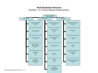
Work Breakdown Structure Application Example. Problem: Create the WBS for a temperature monitoring system design. The system is conceptualized to have the following components:. Ambient Temperature Sensor The Temperature Conversion Unit converts the Sensor output to analog voltage signal

E N D
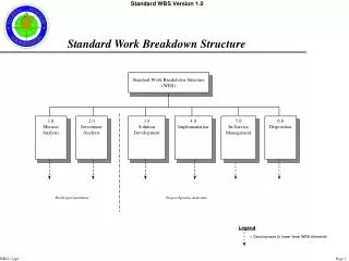
Work Breakdown Structure Application Example Problem: Create the WBS for a temperature monitoring system design.
The system is conceptualized to have the following components: • Ambient Temperature Sensor • The Temperature Conversion Unit converts the Sensor output to analog voltage signal • The analog voltage signal is converted to digital signal in Binary number format • The Binary Number is converted to Binary-Coded-Decimal (BCD) number format • The BCD Number enters into the 7-Segment LED Drive Circuit • The 7-Segment Drive Circuit drives the LED Displayers to display the temperature being measured • Power Supply converts 120 AC Voltage from the power source to 5-V DC to power all circuit units
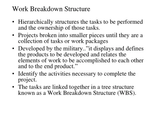
The main tasks in this project are: • The analog interface circuitry. • The LED & Driver Circuitry. • Integration and Test.
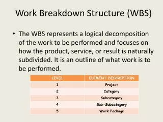
The Table of Work Breakdown Structure (WBS) for the Temperature Measurement System is shown below:
The WBS table shows, for the activity Interface Circuitry: • The first activity is 1.1, Design Circuitry: • Activity: Design Circuitry • Description: Complete the detailed design and verify it. • Deliverables/Checkpoints: 1) Circuit schematic, and 2) Verify in simulation. • Duration: 14 days. • People: Jana (1), Rob (1) • Resources: PC, SPICE Simulator • Predecessors: none
After the circuitry has been designed and verified via simulation… • The next activity is 1.2, Purchase components: • Activity: Purchase components • Description: Complete the purchase • Deliverables/Checkpoints: 1) identify parts, 2) order parts, and 3) receive and check the parts list • Duration: 10 days. • People: Rob • Resources: • Predecessors: 1.1
The number in the parenthesis next to the person’s name indicates the responsibility level • For example, Rob(1) indicates that Rob is the first responsible person, Jana(2) indicates she is the secondary responsible person…