Download
1 / 10
130 likes | 523 Views
Digital Electronics Logic Gates. Logic gates work with the voltage level of the signals. They are discrete devices that understand only a High voltage level and Low voltage level. For certain digital devices a High is 5 Volts and Low is 0 Volts.

E N D
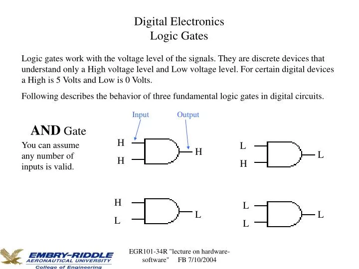
Digital Electronics Logic Gates Logic gates work with the voltage level of the signals. They are discrete devices that understand only a High voltage level and Low voltage level. For certain digital devices a High is 5 Volts and Low is 0 Volts. Following describes the behavior of three fundamental logic gates in digital circuits. Input Output AND Gate H You can assume any number of inputs is valid. L H L H H H L L L L L EGR101-34R "lecture on hardware-software" FB 7/10/2004
OR Gate You can assume any number of inputs is valid. H L H H H H H L H L L L EGR101-34R "lecture on hardware-software" FB 7/10/2004
Inverter Gate One input, One output L H L H EGR101-34R "lecture on hardware-software" FB 7/10/2004
Simple Hardware-Software system In computer systems, the integration and cooperation of hardware and software is essential to the operation of the system. In many automated systems the operation is essentially for the computer system to detect an event, analyze the event, and react to that event based on the requirement of the system. As a simple description of the operation, sensors can be connected to the input of an electronic circuit. The state of the out put of this circuit can be written to a location in the memory. Software will read this status and makes a decision of what needs to be done in order to respond to the activation of this sensor. Once that is determined, the software can activate another hardware circuit; for example turn on or turn off a switch. EGR101-34R "lecture on hardware-software" FB 7/10/2004
Example: As a part of an aircraft’s functional monitoring system, the status of the the landing gears must be known prior to the landing. The gears must be extended and locked into position. One design could be that the sensors that are connected to the gears will change their output level from Low (0 volt) to High (5 volts) when the gear is extended and is locked, otherwise they stay Low. Let us assume that there are six sensors, two for each gear, one to detect the extension of a gear and the other to detect if the gear is locked into position. These sensors are connected to a digital hardware circuit which takes these inputs and outputs a High (5 volts), if all gears are extended and are locked. The state of this output is written to a location in a memory of the onboard computer. The software responsible for checking the functionality and status of the aircraft during landing process will read this location and based on the what it reads (for example OK or NOT OK) it activates a switch to turn on the green landing gear light (indicating that the gears are extended and locked) or the red landing gear light (indicating a problem with the landing gears). The pilot checks the light and takes corrective action. EGR101-34R "lecture on hardware-software" FB 7/10/2004
A possible solution: Hardware side LLGE is the sensor indicating that the Left Landing Gear is Extended LLGL is the sensor indicating that the Left Landing Gear is Locked So on for the rest of the sensors (F-Front, R-Right) addresses Memory locations n n+1 n+2 n+3 …. …. content LLGE LLGL content OK or NOT OK FLGE content FLGL …. …. RLGE …. RLGL EGR101-34R "lecture on hardware-software" FB 7/10/2004
A possible solution continues: Software side A solution is demonstrated by the following activity diagram and the corresponding pseudo code. Once the design is completed, software can be developed in an appropriate programming language. Note: keep in mind that there are concurrent activities while this system is checking the landing gear status. For example, as the pilot sees the red light indicating that the landing gear status is not ok, he will be trying to extend and lock the landing gears in place while there is still time to land. The computer system constantly is checking the landing gear status. EGR101-34R "lecture on hardware-software" FB 7/10/2004
Start Read the memory location n+2 is There Still time To land Is It OK No Yes Yes No Turn the Green indicator light ON Turn the RED indicator light ON Next function for Landing Next function for abort landing A possible solution continues: Software side EGR101-34R "lecture on hardware-software" FB 7/10/2004
A possible solution continues: Software side, pseudo code Read the appropriate memory location for landing gear status if the status is OK turn the GREEN indicator light on in the cockpit go to do the next function for landing else (status is NOT OK) check timer to see if there is still time for landing if there is still time go back to read the memory location again else turn the RED indicator light on in the cockpit go to do next function for abort landing EGR101-34R "lecture on hardware-software" FB 7/10/2004
Software development process(same process can be followed for hardware) A software system should be developed by following the development cycle below. • Gather requirement specification (what is this system supposed to do?) • Analyze the specification for possible solutions (what are the ways that this system can be designed. Pick the best solution) • Design the system (decompose the problem into smaller problems and solve each problem, then bring the solutions together for the complete solution) • Implementation (write a computer program to do the job) • Test (document and test the different scenarios that could make this system fail and fix the software BUGS) • Maintain the system (this comes after the product is completed and deployed) EGR101-34R "lecture on hardware-software" FB 7/10/2004