Download
1 / 1
30 likes | 230 Views
Advisors: Professor Peroulis , Professor Scott . Antenna Design Siyang Liu, Tao Yang. Our goal is to design an antenna with high efficiency and match the impedance with the circuit.

E N D
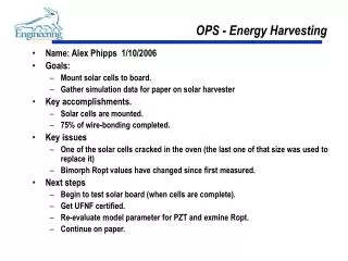
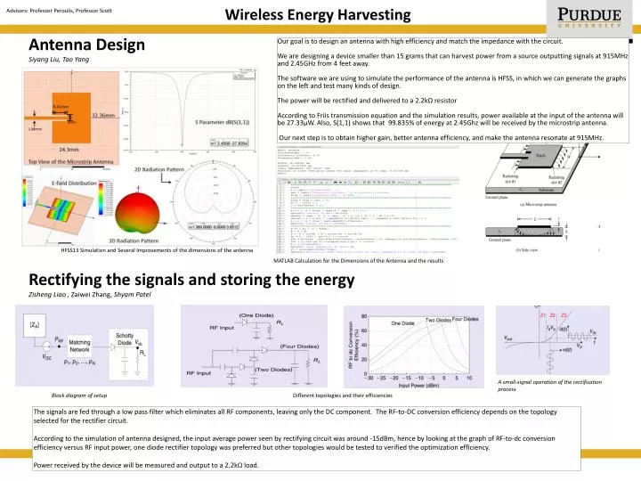
Advisors: Professor Peroulis, Professor Scott Antenna Design Siyang Liu, Tao Yang Our goal is to design an antenna with high efficiency and match the impedance with the circuit. We are designing a device smaller than 15 grams that can harvest power from a source outputting signals at 915MHz and 2.45GHzfrom 4 feet away. The software we are using to simulate the performance of the antenna is HFSS, in which we can generate the graphs on the left and test many kinds of design. The power will be rectified and delivered to a 2.2kΩ resistor According to Friis transmission equation and the simulation results, power available at the input of the antenna will be 27.33μW. Also, S(1,1) shows that 99.835% of energy at 2.45Ghz will be received by the microstrip antenna. Our next step is to obtain higher gain, better antenna efficiency, and make the antenna resonate at 915MHz. HFSS13 Simulation and Several Improvements of the dimensions of the antenna Wireless Energy Harvesting MATLAB Calculation for the Dimensions of the Antenna and the results Rectifying the signals and storing the energy Zisheng Liao , Zaiwei Zhang, Shyam Patel A small-signal operation of the rectification process Block diagram of setup Different topologies and their efficiencies The signals are fed through a low pass filter which eliminates all RF components, leaving only the DC component. The RF-to-DC conversion efficiency depends on the topology selected for the rectifier circuit. According to the simulation of antenna designed, the input average power seen by rectifying circuit was around -15dBm, hence by looking at the graph of RF-to-dc conversion efficiency versus RF input power, one diode rectifier topology was preferred but other topologies would be tested to verified the optimization efficiency. Power received by the device will be measured and output to a 2.2kΩ load.