Download
1 / 16
160 likes | 265 Views
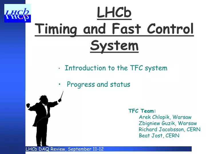
LHCb Timing and Fast Control System. Introduction to the TFC system Progress and status. TFC Team: Arek Chlopik, Warsaw Zbigniew Guzik, Warsaw Richard Jacobsson, CERN Beat Jost, CERN. LHCb Read-out. Unique feature : Two levels of high-rate triggers

E N D
LHCb Timing and Fast Control System • Introduction to the TFC system • Progress and status • TFC Team: • Arek Chlopik, Warsaw • Zbigniew Guzik, Warsaw • Richard Jacobsson, CERN • Beat Jost, CERN
LHCb Read-out • Unique feature : Two levels of high-rate triggers • Level-0 (40 MHz --> 1.1 MHz Accept rate) • Level-1 (1.1 MHz --> 40-100 kHz Accept rate) Data rates LHC-B Detector VDET TRACK ECAL HCAL MUON RICH 40 MHz Level 0 Trigger 40 TB/s 1 MHz Level-0 Front-End Electronics Level-1 Timing & Fast Control L0 Fixed latency 4.0 ms 1 TB/s 40 kHz L1 Level 1 Trigger LAN 1 MHz Front-End Multiplexers (FEM) Front End Links 6-15 GB/s Variable latency <1 ms RU RU RU Read-out units (RU) Throttle Read-out Network (RN) 6-15 GB/s SFC SFC Sub-Farm Controllers (SFC) Variable latency L2 ~10 ms L3 ~200 ms Control & Monitoring Storage 50 MB/s Trigger Level 2 & 3 Event Filter CPU CPU CPU CPU
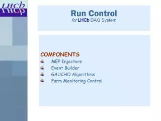
Timing and Fast Control • Consists of: • - RD12 TTC distribution system: • TTCtx’s • Tree-couplers • TTCrx’s • - Components specific to LHCb: • Readout Supervisors • TFC Switch • Throttle Switches • Throttle ORs
Use of TTC • Timing, Trigger and Control distributed using the TTC system: • Channel A used to distribute (accept/reject signal) • L0 trigger (40 MHz --> 1.1 MHz accept rate) • Channel B used to distribute (short broadcasts): • L1 trigger (1.1 MHz --> 40-100 kHz accept rate) • Bunch/Event Counter Resets • Control commands (FE resets, calibration pulses) • Broadcast order is handled according to a priority scheme • Usage of the 6 (+2) user bits in the short broadcasts:
LHCb specific components • Readout Supervisor “Odin” • all mastership in single module • TFC switch • Clock, trigger and command distribution and support partitioning • Throttle switches (L0 & L1) and Throttle ORs • Throttle feed-back
ECS Throttles LHC clock L0 L1 - Single module - TTC encoding Trigger generator ECS interface - Clock distribution - L0 handling & distribution - L1 handling & distribution L1 Derandomizer - L1 derandomization Trigger controller - Auto-trigger generator Reset/command generator - Trigger controller - Reset/cmd generator RS Front-End L0/L1 - “RS Front-End” TTC encoder - ECS interface Ch A/B DAQ Readout Supervisor “Odin” • Designed with emphasis on: • Versatility - to support many different types of running modes • Functionality easily added and modified.
LHCb partitioning • Partition (TFC)Def.Generic term for a configurable ensemble of parts of a sub-detector, an entire sub-detector or a combination of sub-detectors that can be run in parallel, independently and with a different timing, trigger and control configuration than any other partition. • Option: 16 or 32 concurrent partitions • Crucial: Equal internal propagation delays. If skew too large, FE will suffer from timing alignment problems when using different RS’. Pool of Readout Supervisors Partition A Partition B TTC information encoded electrical TFC Switch Front-Ends grouped by TTCtx/Optical couplers to partition elements
Buffer overflows • Throttle signals fed back electrically to the RS in control of the partition with data congestion • Two Throttle Switches: • Throttle signals to the L0 trigger • Throttle signals to the L1 trigger • All Throttle Switches and ORs will log throttle history Pool of Readout Supervisors Throttle Switch Throttle signals Partition A Partition B Front-Ends etc grouped by Throttle ORs i.e. ~Throttle Switches
Progress and Status • In view of the TDR, the aims of this year are to: • Design the TFC components specific to LHCb • Review the TFC architecture and components • Layout the first prototype of the TFC Switch and the RS • Simulate the RS at several levels • Test the way the TFC architecture exploits the TTC system • Produce a first prototype of the TFC Switch and the RS • Test critical points of the TFC Switch and the RS • Overview of work schedule for 2001: • Except for delays in the area of testing TTC system, schedule well maintained.
TFC Switch (Progress and Status) • Reviewed November 8, 2000 (together with TFC architecture and Throttle Switches) • very well received • First prototype was ready in April-May. Main aim with prototype was to measure the two crucial quantities: • Time skew between paths (aimed at <100 ps). • Jitter (aimed at 50 ps)
TFC Switch (Progress and Status) • All measurements carried out successfully • Jitter at the output ~80 - 100 ps. Jitter from generator ~50 ps • Maximum skew between all inputs to each multiplexer is between 100 - 400 ps • Skews between between output paths (multiplexers to output) was very large (-> 4ns) • A few mistakes were discovered in the routing when equalizing the paths. • The mistakes + dielectric characteristics can account for the skews measured on the input and the ouput paths. • The intrinsic propagation delay of the multiplexers vary between 400 - 1000 ps. Specs claim maximum 850 ps. • Comparing line lengths with measured propagation delays shows that the signal speedis ~40% slower than the “ideal” 5ns/m. This is consistent in all measurements. • The measurements show that the performance with respect to skew is not satisfactory. Solution: • Route all lines on board layers with equal dielectric characteristics • Add appropriate delay lines at the outputs to compensate for the inevitable intrinsic skew due to the components. • Problem with temperature dependence of delay chips • Each board needs calibration. • Input and output coupling capacitors with less tolerance to improve signal shape. • Switch has still to be tested with CC-PC and in full TTC setup. • The first prototype will be sufficient for tests of the first prototype of the RS
RS “Odin” (Progress and Status) • Specifications ready end of last year - almost entirely based on FPGA • Specs, logical design and first draft of schematics reviewed April 4, 2001. • Very well received • Importance of simulation emphasized. • Specs have been simulated in a high level behavioral model with a behavioral model of the LHC machine, trigger decision unit, and FE, using Visual HDL
RS “Odin” (Progress and Status) • The FPGA designs have been simulated using MaxPlus • To check the FPGA designs and crosscheck the MaxPlus simulation, some of the blocks have been simulated at gate level using Leapfrog. • The behavioral model of the LHC machine, the trigger decision units, and the FE have been refined in order to support a simulation of the real RS design. The behavioral model of the RS is currently being replaced in Visual HDL block by block by the FPGA designs at gate level including all delays. • The entire L0 path (except TTC encoder) has been simulated. Shows that the current design, using three or four clocks (different level of pipelining) works. L0 handling I/O L0 pipeline
RS “Odin” (Progress and Status) • The interface to the L0 and the L1 trigger Decision Units have been agreed on. • RS Minimal Version currently in production: • Almost all functionality but not the “RS internal FE” and fewer counters. • Aim with first prototype is: • Verify that the FPGAs are sufficiently fast with safe margin for the functions requiring synchronous operation. • Measure performance and check concurrent operations of the many functions
TTC tests (Progress and Status) • The need for 1.1 MHz short broadcast transmission on channel B is a crucial point to test. Lacking RS, a test bench was setup using existing equipment: • Using a scope (before the TTCpr was available) shows no problem transmitting 1.1MHz short broadcasts. 1.6 MHz was measured. Data integrity not tested! • Since the encoder circuit in the TTCvx will implemented in the RS and we will use TTCtx the test bench has also allowed us to gain experience and study the performance. • TTCpr is designed to receive ATLAS L1A: • Help from ATLAS to modify the code of the onboard FPGA to receive short broadcasts. • Two problems remain: • The transfer of the short broadcasts into the host PC does not work properly. • Testing the same throughput (1.1 MHz * 16 bits) using the ATLAS version of the FPGA (long broadcasts) shows problems above ~100 kHz. EventIDs show jumps. PC not capable to cope? ALEPH FIC TTCvi TTCvx TTCtx TTCpr VME
Conclusions • LHCb TFC system architecture and specific components have been reviewed in two reviews. • The partitioning concept well integrated. • The first designs and layouts of the LHCb specific components are ready. • Detailed simulation of RS continuing. • The first prototype of the TFC Switch built and the first RS in production. • The results of the tests of the first TFC Switch are very useful. • The first tests with the TTC system show positive results. Work going on with the TTCpr. • When the RS is ready, it will replace the TTCvi + TTCvx in the test bench