Download
1 / 51
1.07k likes | 2.23k Views
Chapter 3: Steady uniform flow in open channels. Learning outcomes. By the end of this lesson, students should be able to: Understand the concepts and equations used in open channel flow Determine the velocity and discharge using Chezy’s & Manning’s equation

E N D
Learning outcomes • By the end of this lesson, students should be able to: • Understand the concepts and equations used in open channel flow • Determine the velocity and discharge using Chezy’s & Manning’s equation • Able to solve problems related to optimum cross section in both conduits and open channel UiTMSarawak/ FCE/ BCBidaun/ ECW301
Introduction • Comparison between full flow in closed conduit and flow in open channel UiTMSarawak/ FCE/ BCBidaun/ ECW301
Flow classification • Turbulent flow: • Characterized by the random and irregular movement of fluid particles. • Movement of fluid particles in turbulent flow is accompanied by small fluctuations in pressure. • Flows in open channel are mainly turbulent. • E.g. Hydraulic jump from spillway, Flow in fast flowing river UiTMSarawak/ FCE/ BCBidaun/ ECW301
Flow classification • Laminar flow: • Flow characterized by orderly movement of fluid particles in well defined paths. • Tends to move in layers. • May be found close to the boundaries of open channel. UiTMSarawak/ FCE/ BCBidaun/ ECW301
For flow in pipes UiTMSarawak/ FCE/ BCBidaun/ ECW301
Flow in open channel UiTMSarawak/ FCE/ BCBidaun/ ECW301
Steady uniform flow • Flow parameters do not change wrt space (position) or time. • Velocity and cross-sectional area of the stream of fluid are the same at each cross-section. • E.g. flow of liquid through a pipe of uniform bore running completely full at constant velocity. UiTMSarawak/ FCE/ BCBidaun/ ECW301
Steady non-uniform flow • Flow parameters change with respect to space but remain constant with time. • Velocity and cross-sectional area of the stream may vary from cross-section to cross-section, but, for each cross-section, they will not vary with time. • E.g. flow of a liquid at a constant rate through a tapering pipe running completely full. UiTMSarawak/ FCE/ BCBidaun/ ECW301
Unsteady uniform flow • Flow parameters remain constant wrt space but change with time. • At a given instant of time the velocity at every point is the same, but this velocity will change with time. • E.g. accelerating flow of a liquid through a pipe of uniform bore running full, such as would occur when a pump is started. UiTMSarawak/ FCE/ BCBidaun/ ECW301
Unsteady non-uniform flow • Flow parameters change wrt to both time & space. • The cross-sectional area and velocity vary from point to point and also change with time. • E.g. a wave travelling along a channel. UiTMSarawak/ FCE/ BCBidaun/ ECW301
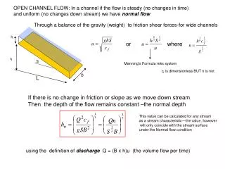
Flow classification • Normal depth – depth of flow under steady uniform condition. • Steady uniform condition – long channels with constant cross-sectional area & constant channel slope. • Constant Q • Constant terminal v • Therefore depth of flow is constant (yn or Dn) UiTMSarawak/ FCE/ BCBidaun/ ECW301
Total energy line for flow in open channel UiTMSarawak/ FCE/ BCBidaun/ ECW301
From the figure : • Water depth is constant • slope of total energy line = slope of channel • When velocity and depth of flow in an open channel change, then non-uniform flow will occur. UiTMSarawak/ FCE/ BCBidaun/ ECW301
Flow classification • Non uniform flow in open channels can be divided into two types: • Gradually varied flow, GVF • Where changes in velocity and depth of flow take place over a long distance of the channel • Rapidly varied flow, RVF • Where changes in velocity and depth of flow occur over short distance in the channel UiTMSarawak/ FCE/ BCBidaun/ ECW301
Non-uniform flow UiTMSarawak/ FCE/ BCBidaun/ ECW301
Total energy line for flow in open channel UiTMSarawak/ FCE/ BCBidaun/ ECW301
Continuity equation: • For rectangular channel: • Express as flow per unit width, q: UiTMSarawak/ FCE/ BCBidaun/ ECW301
Momentum equation • Produced by the difference in hydrostatic forces at section 1 and 2: • Resultant force, UiTMSarawak/ FCE/ BCBidaun/ ECW301
Energy equation • But hydrostatic pressure at a depth x below free surface, • Therefore, • Energy equation rewritten as, UiTMSarawak/ FCE/ BCBidaun/ ECW301
Energy equation • For steady uniform flow, • Therefore the head loss is, • And energy equation reduces to, • Known as specific energy, E, (total energy per unit weight measured above bed level), UiTMSarawak/ FCE/ BCBidaun/ ECW301
Geometrical properties of open channels • Geometrical properties of open channels: • Flow cross-sectional area, A • Wetted perimeter, P • Hydraulic mean depth, m UiTMSarawak/ FCE/ BCBidaun/ ECW301
A – covers the area where fluid takes place. • P – total length of sides of the channel cross-section which is in contact with the flow. D B UiTMSarawak/ FCE/ BCBidaun/ ECW301
Example 3.1 Determine the hydraulic mean depth, m, for the trapezoidal channel shown below. UiTMSarawak/ FCE/ BCBidaun/ ECW301
Chezy’s coefficient, C • From chapter 1, • Rearranging to fit for open channel, the velocity: • Where Chezy roughness coefficient, • For open channel i can be taken as equal to the gradient of the channel bed slope s. Therefore, UiTMSarawak/ FCE/ BCBidaun/ ECW301
Manning’s n • Introduced roughness coefficient n of the channel boundaries. UiTMSarawak/ FCE/ BCBidaun/ ECW301
Example 3.2 Calculate the flow rate, Q in the channel shown in Figure 3.5, if the roughness coefficient n = 0.025 and the slope of the channel is 1:1600. UiTMSarawak/ FCE/ BCBidaun/ ECW301
Example 3.3 • Determine the flow velocity, v and the flow rate for the flow in open channel shown in the figure. The channel has a Manning’s roughness n = 0.013 and a bed slope of 1:2000. B 2.75 m 900 UiTMSarawak/ FCE/ BCBidaun/ ECW301
Example 3.4 (Douglas, 2006) • An open channel has a cross section in the form of trapezium with the bottom width B of 4 m and side slopes of 1 vertical to 11/2 horizontal. Assuming that the roughness coefficient n is 0.025, the bed slope is 1/1800 and the depth of the water is 1.2 m, find the volume rate of flow Q using a. Chezy formula (C=38.6) b. Manning formula UiTMSarawak/ FCE/ BCBidaun/ ECW301
Example 3.5 (Munson, 2010) • Water flows along the drainage canal having the properties shown in figure. The bottom slope so = 0.002. Estimate the flow rate when the depth is 0.42 m . UiTMSarawak/ FCE/ BCBidaun/ ECW301
Example 3.6 (Bansal, 2003) Find the discharge of water through the channel shown in figure. Take the value of Chezy’s constant = 60 and slope of the bed as 1 in 2000. A D 1.2 m C 2.7 m B 1.5 m E UiTMSarawak/ FCE/ BCBidaun/ ECW301
Example 3.8 (Bansal, 2003) Find the diameter of a circular sewer pipe which is laid at a slope of 1 in 8000 and carries a discharge of 800 L/s when flowing half full. Take the value of Manning’s n = 0.020. D d UiTMSarawak/ FCE/ BCBidaun/ ECW301
Optimum cross-sections for open channels • Optimum cross section – producing Qmax for a given area, bed slope and surface roughness, which would be that with Pmin and Amin therefore tend to be the cheapest. • Qmax : Amin, Pmin UiTMSarawak/ FCE/ BCBidaun/ ECW301
Example 3.9 Given that the flow in the channel shown in figure is a maximum, determine the dimensions of the channel. UiTMSarawak/ FCE/ BCBidaun/ ECW301
Optimum depth for non-full flow in closed conduits • Partially full in pipes can be treated same as flow in an open channel due to presence of a free water surface. UiTMSarawak/ FCE/ BCBidaun/ ECW301
Optimum depth for non-full flow in closed conduits • Flow cross sectional area, • Wetted perimeter, UiTMSarawak/ FCE/ BCBidaun/ ECW301
Optimum depth for non-full flow in closed conduits • Under optimum condition, vmax, • Substituting & simplifying, UiTMSarawak/ FCE/ BCBidaun/ ECW301
Optimum depth for non-full flow in closed conduits • Hence depth, D, at vmax, • Using Chezy equation, UiTMSarawak/ FCE/ BCBidaun/ ECW301
Optimum depth for non-full flow in closed conduits • Qmax occurs when (A3/P) is maximum, • Substituting & simplifying, • Therefore depth at Qmax, UiTMSarawak/ FCE/ BCBidaun/ ECW301
OCT 2010 • Analysis of flow in open channels is based on equations established in the study of fluid mechanics. State the equations. UiTMSarawak/ FCE/ BCBidaun/ ECW301
OCT 2010 • Determine the discharge in the channel (n = 0.013) as shown in Figure Q3(b). The channel has side slopes of 2 : 3 (vertical to horizontal) and a slope of 1 : 1000. Determine also the discharge if the depth increases by 0.1 m by using Manning's equation. UiTMSarawak/ FCE/ BCBidaun/ ECW301
OCT 2010 • State the differences between : i) Steady and unsteady flow ii) Uniform and non-uniform flow UiTMSarawak/ FCE/ BCBidaun/ ECW301