Download
1 / 45
600 likes | 1.47k Views
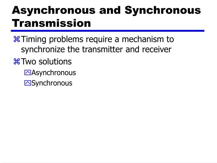
Asynchronous and Synchronous Transmission. Timing problems require a mechanism to synchronize the transmitter and receiver Two solutions Asynchronous Synchronous. Asynchronous. Data transmitted on character at a time 5 to 8 bits Timing only needs maintaining within each character

E N D
Asynchronous and Synchronous Transmission • Timing problems require a mechanism to synchronize the transmitter and receiver • Two solutions • Asynchronous • Synchronous
Asynchronous • Data transmitted on character at a time • 5 to 8 bits • Timing only needs maintaining within each character • Resync with each character
Asynchronous - Behavior • In a steady stream, interval between characters is uniform (length of stop element) • In idle state, receiver looks for transition 1 to 0 • Then samples next seven intervals (char length) • Then looks for next 1 to 0 for next char • Simple • Cheap • Overhead of 2 or 3 bits per char (~20%) • Good for data with large gaps (keyboard)
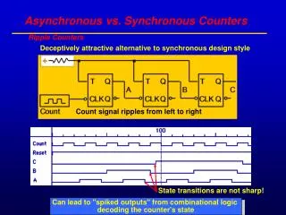
Synchronous - Bit Level • Block of data transmitted without start or stop bits • Clocks must be synchronized • Can use separate clock line • Good over short distances • Subject to impairments • Embed clock signal in data • Manchester encoding • Carrier frequency (analog)
Synchronous - Block Level • Need to indicate start and end of block • Use preamble and postamble • e.g. series of SYN (hex 16) characters • e.g. block of 11111111 patterns ending in 11111110 • More efficient (lower overhead) than async
Flow Control • Ensuring the sending entity does not overwhelm the receiving entity • Preventing buffer overflow • Transmission time • Time taken to emit all bits into medium • Propagation time • Time for a bit to traverse the link
Stop and Wait • Source transmits frame • Destination receives frame and replies with acknowledgement • Source waits for ACK before sending next frame • Destination can stop flow by not send ACK • Works well for a few large frames
Fragmentation • Large block of data may be split into small frames • Limited buffer size • Errors detected sooner (when whole frame received) • On error, retransmission of smaller frames is needed • Prevents one station occupying medium for long periods • Stop and wait becomes inadequate
Sliding Windows Flow Control • Allow multiple frames to be in transit • Receiver has buffer W long • Transmitter can send up to W frames without ACK • Each frame is numbered • ACK includes number of next frame expected • Sequence number bounded by size of field (k) • Frames are numbered modulo 2k
Sliding Window Enhancements • Receiver can acknowledge frames without permitting further transmission (Receive Not Ready) • Must send a normal acknowledge to resume • If duplex, use piggybacking • If no data to send, use acknowledgement frame • If data but no acknowledgement to send, send last acknowledgement number again, or have ACK valid flag (TCP)
Error Detection • Additional bits added by transmitter for error detection code • Parity • Value of parity bit is such that character has even (even parity) or odd (odd parity) number of ones • Even number of bit errors goes undetected
Cyclic Redundancy Check • For a block of k bits transmitter generates n bit sequence • Transmit k+n bits which is exactly divisible by some number • Receive divides frame by that number • If no remainder, assume no error • For math, see Stallings chapter 7
Error Control • Detection and correction of errors • Lost frames • Damaged frames • Automatic repeat request • Error detection • Positive acknowledgment • Retransmission after timeout • Negative acknowledgement and retransmission
Automatic Repeat Request (ARQ) • Stop and wait • Go back N • Selective reject (selective retransmission)
Stop and Wait • Source transmits single frame • Wait for ACK • If received frame damaged, discard it • Transmitter has timeout • If no ACK within timeout, retransmit • If ACK damaged,transmitter will not recognize it • Transmitter will retransmit • Receive gets two copies of frame • Use ACK0 and ACK1
Stop and Wait - Pros and Cons • Simple • Inefficient
High Level Data Link Control • HDLC • ISO 33009, ISO 4335
HDLC Station Types • Primary station • Controls operation of link • Frames issued are called commands • Maintains separate logical link to each secondary station • Secondary station • Under control of primary station • Frames issued called responses • Combined station • May issue commands and responses
HDLC Link Configurations • Unbalanced • One primary and one or more secondary stations • Supports full duplex and half duplex • Balanced • Two combined stations • Supports full duplex and half duplex
HDLC Transfer Modes (1) • Normal Response Mode (NRM) • Unbalanced configuration • Primary initiates transfer to secondary • Secondary may only transmit data in response to command from primary • Used on multi-drop lines • Host computer as primary • Terminals as secondary
HDLC Transfer Modes (2) • Asynchronous Balanced Mode (ABM) • Balanced configuration • Either station may initiate transmission without receiving permission • Most widely used • No polling overhead
HDLC Transfer Modes (3) • Asynchronous Response Mode (ARM) • Unbalanced configuration • Secondary may initiate transmission without permission form primary • Primary responsible for line • rarely used
Frame Structure • Synchronous transmission • All transmissions in frames • Single frame format for all data and control exchanges
Frequency Division Multiplexing • FDM • Useful bandwidth of medium exceeds required bandwidth of channel • Each signal is modulated to a different carrier frequency • Carrier frequencies separated so signals do not overlap (guard bands) • e.g. broadcast radio • Channel allocated even if no data
Analog Carrier Systems • AT&T (USA) • Hierarchy of FDM schemes • Group • 12 voice channels (4kHz each) = 48kHz • Range 60kHz to 108kHz • Supergroup • 60 channel • FDM of 5 group signals on carriers between 420kHz and 612 kHz • Mastergroup • 10 supergroups
Synchronous Time Division Multiplexing • Data rate of medium exceeds data rate of digital signal to be transmitted • Multiple digital signals interleaved in time • May be at bit level of blocks • Time slots preassigned to sources and fixed • Time slots allocated even if no data • Time slots do not have to be evenly distributed amongst sources
Framing • No flag or SYNC characters bracketing TDM frames • Must provide synchronizing mechanism • Added digit framing • One control bit added to each TDM frame • Looks like another channel - “control channel” • Identifiable bit pattern used on control channel • e.g. alternating 01010101…unlikely on a data channel • Can compare incoming bit patterns on each channel with sync pattern
ADSL Design • Asymmetric • Greater capacity downstream than upstream • Frequency division multiplexing • Lowest 25kHz for voice • Plain old telephone service (POTS) • Use echo cancellation or FDM to give two bands • Use FDM within bands • Range 5.5km
xDSL • High data rate DSL • Single line DSL • Very high data rate DSL