Download
1 / 47
480 likes | 509 Views
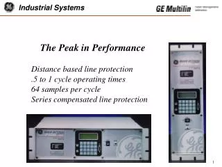
Distance based line protection. .5 to 1 cycle operating times. 64 samples per cycle. Series compensated line protection. The Peak in Performance. Protection Features. Application on any voltage line Single and three phase tripping Lines with series capacitor compensation

E N D
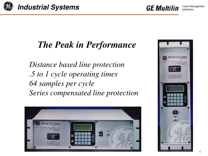
Distance based line protection .5 to 1 cycle operating times 64 samples per cycle Series compensated line protection The Peak in Performance
Protection Features • Application on any voltage line • Single and three phase tripping • Lines with series capacitor compensation • Four zones of phase and ground distance functions • Pilot ground directional overcurrent • Overcurrent backup • Selectable pilot scheme logics • Programmable logic • Programmable I/O • Out of Step Trip logic (Optional)
Protection Algorithm Advancements • New Fourier calculation approach • Fourier built from phaselets • Fourier data purged by Fault Detector pickup • Adaptive Zone 1 reach • Reach “grows” from 33% to 100% of setting
Modified Fourier Calculation • High Speed Sampling • Digital Mimic • Phaselet Calculation • Variable Window
Mimic Algorithm Time Domain: Sampled Data:
Phaselet Definition • Phaselets are partial sums of the products of the waveform samples and the sine/cosine coefficients. • Input signals are sampled 64 times per cycle; protection algorithms are executed 16 times per cycle. • Groups of phaselets may be scaled and added together to create a phasor.
Phasor Calculation Phaselets are converted to phasors by the following: Where: n = Phasor index (N/P) W = Window size in samples
Phasor Calculation For a one cycle window, the Fourier calculation becomes:
Variable Reach Zone 1 Zone 1 reach is set to 90 % of ZL. WINDOW SIZE% OF SET REACH 1/16 Cycle 0 (can not operate) 1/8 Cycle 33% 3/16 Cycle 65% 1/4 Cycle 75% 5/16 Cycle 83% 1/2 Cycle 90% > 1/2 Cycle 100%
Overcurrent Functions • Fault Detector • Distance function supervision • Phase & ground instantaneous units • Ground time overcurrent (TOC) • Unbalanced current alarm • Instantaneous & TOC may be directionally controlled. • Overload Alarm
Voltage Functions • 3 single phase undervoltage detectors • Positive sequence undervoltage detector • 3 single phase over/undervoltage detectors • Potential fuse failure detection logic • Optional synch check voltage for recloser • Optional positive sequence overvoltage functions
Directional Functions • Forward and reverse negative sequence directional functions with adjustable compensation • For use in Ground Directional Over Current protection (GDOC) and to supervise instantaneous & time over current functions
Impedance Measurement • 4 Zones of phase and ground mho distance functions • Zone 4 is reversible • Zones 2, 3 & 4 include independent phase and ground timers for step distance backup • Zone 1 ground may be either a mho or reactance characteristic with adaptive mho supervision
Out-of-Step Functions • Out-of-Step Blocking • Out-of-Step Tripping 3 independent positive sequence mho distance characteristics. Option to trip entering inner characteristic, or leaving outer characteristic. • Extended oscillography data capture
Pilot Schemes • Blocking • PUTT • POTT1 - Standard permissive overreaching • POTT2 - POTT with blocking functions to improve transient blocking performance • Hybrid - Includes Echo/Repeat logic and optional weak infeed tripping • Step Distance backup is included in all schemes • Programmable logic
Other Features • 4 Setting Groups • Line Pickup Logic • Remote Open Detection for faster clearing of unbalanced faults • Continuous Monitor • PT Fuse Failure Detection
Monitoring Features • Fault location calculation • Event reporting • Oscillography data capture • Circuit breaker trip coil monitor • Accumulated breaker duty • Relay self test
Metering Features • Local metering on LCD display • Remote metering via communications • True RMS calculation • Current: Ia, Ib, Ic, and 3I0 • Voltage: Vag, Vbg, Vcg • Frequency • Three phase watts and vars
RMS Metering Values • Compute RMS by taking the average of squares of each sample data • RMS values are computed 16 time per cycle based on a sliding window of one cycle
Communications Features • ASCII and GE-modem protocols standard • Plug-in communications protocol converter • Front nine pin RS232 port • Rear 25 pin RS232 or 4 pin Phoenix RS485 • Optional second rear 25 pin RS232/RS485 • Rear ports user selectable as RS232 or RS485 • All ports independently settable
Programmable Logic Summary • Maximum of 40 logic gates (AND, OR, NOT) Maximum of 4 inputs per gate • Maximum of 8 programmable timers Pickup/dropout range of 0 to 60 seconds in 1 ms steps • Maximum of 8 counters and latches • Fully assignable I/O
Programmable Logic, Inputs, and Outputs SCHEME LOGIC MEASURING FUNCTIONS PROGRAMMABLE OUTPUTS PROGRAMMABLE INPUTS PROGRAMMABLE LOGIC
Expression Builder User defines logic which program then builds into Boolean expression for downloading to ALPS
Recloser (Optional) • Single breaker reclosing • Programmable up to 4 reclose attempts • Optional synch check/voltage supervision
Local Interface • Multi-line 20 character LCD display for settings, fault data (faulted phases, trip type, fault location) and metering data • 2 LED’s - one to indicate system status, one to indicate unacknowledged trip data • Full keypad standard
Password Protection REMOTEKEYPAD VIEW SETTING SETTING NONE or CONTROL CONTROL MASTER MASTER
LOGIN QUIT PASSWORD VALUES READINGS FAULT EVENTS OPEN CLOSE ENOUT DISOUT STATUS SHOWSET SET MODEL DATE ASCII Command List ( 1 of 2 )
TIME GROUP TRIGGER RELTEST MMIPASS UNITID STLINID DIGTST REQTOC PLAYBACK DATARESET OUTPUTS INPUTS ACCESS END HELP ASCII Command List ( 2 of 2 )
Oscillography Data • 64 sample per cycle data including: Currents & voltages Contact input & output status Internal sequence of events • Flexible triggering & event storage 2 events at 72 cycles to 16 events at 9 cycles • Optional additional memory • Files may be stored in COMTRADE format
Oscillography Data Playback The ALPS relay has the ability to replay stored oscillography data. The data must be in the ALPS data format. The data may be fault data stored in the relay, or downloaded data stored on a PC. The digital data is run through the ALPS protection algorithms.
Support Software ALPS-LINK: Windows based GEmodem communications ALPS-SET: Windows based settings calculations and file creation ALPS-TEST: Windows based test quantity calculation Xpression Builder: Windows based programmable logic design GE-DATA: Oscillography data analysis
Upgrade Features • Flash memory allows firmware upgrades without changing relay hardware • Plug-in communications module allows for upgrade to future communications protocols
I/O Summary Inputs: Current: Ia, Ib, Ic Voltage: Vag, Vbg, Vcg, optional Vsynch Digital Inputs: 8 programmable for three phase tripping 12 programmable for single phase tripping Demodulated IRIG-B
I/O Summary • Outputs: • 18 programmable contacts for three phase trip • 24 programmable contacts for single phase trip • 2 alarm contacts • (Power Supply and Critical Failure Alarms) • Analog distance to fault (SCADA)
Packaging • Vertical or horizontal mounting • 3RU 19 inch rack mount • 5.25 X 17.25 vertical mount - Sized to fit the cutout of popular EM distance relays • Reversible mounting flanges • All boards may be removed from the front of the case
Contact Ratings • Trip Trip Duty: 30 A for 1 second Continuous Duty: 6 A Pickup Time: < 4 ms • Alarm Make & Carry: 30 A for 1 second Continuous Duty: 6 A Pickup Time: < 8 ms • Channel Control Power Rating: 10 W Pickup Time: < 0.5 ms
AC Ratings • Current Inputs (Nominal 1 or 5A): 3 X rated continuous 100 X rated for one second 50 X rated for 3 seconds • Voltage Inputs: Nominal Voltage: 100 - 120 (Settable) 1.2 X rated continuous 3.5 X rated for one minute, once per hour
DC Ratings • Three models 48 VDC (38.5 - 60.0) 110/125 VDC (88 - 150) 220/250 VDC (176 - 300)
Summary of ALPS Features • High Speed Tripping for Severe Faults • Model for Series Compensated Lines • Extensive Programmable Logic and Flexible I/O • Out of Step Tripping and Extended Oscillography • Flash Memory • Full ASCII Communications • RS485 & Plug in Communication Card • Playback
ALPS* * * * * * * * * * * * D Distance Relay A Revision Level 1 Single phase tripping logic 3 Three phase tripping logic 1 1 Ampere rated current 5 5 Ampere rated current U For applications without Series Capacitors C For applications with Series Capacitors 0 48 VDC battery voltage 1 110/125 VDC battery voltage 2 220/250 VDC battery voltage 1 SCR trip outputs & contact channel interface 2 Contact trip outputs & contact chan nel interface 3 SCR trip outputs & 5V/20mA channel interface 4 Contact trip outputs & 5V/20mA channel interface 2 Front RS232 com port & 1 settable RS232/RS485 rear port (GE-Modem/ASCII) 3 Front RS232 com port & 2 settable RS232/RS485 rear ports (GE-Modem/ASCII) H Horizontal mounting V Vertical mounting S Standard Oscillography Memory E Extended Oscillography Memory 0 No Out of Step Tripping or Positive Sequence Overvoltage 1 With Out of Step Tripping 2 With Positive Sequence Overvolt age units 3 With Positive Sequence Overvoltage units & Out of Step Tripping N No recloser R Recloser without sync-check option S Recloser with synch-check option ALPS Selection Guide EXAMPLE: ALPSDA35U122VE1N = ALPS Digital Line Protection Distance Relay, Revision A, three phase tripping relay, rated at 5 amperes, Without series capacitor protection, 110/125 VDC supply, contact tripping outputs, 2 communications ports, vertical mounting, with extended memory, without OST functions, and without recloser.