Download
1 / 111
2.66k likes | 5.27k Views
Fundamentals of Distance Protection. GE Multilin. Outline. Transmission line introduction What is distance protection? Non-pilot and pilot schemes Redundancy considerations Security for dual-breaker terminals Out-of-step relaying Single-pole tripping Series-compensated lines.

E N D
Fundamentals of Distance Protection GE Multilin
Outline • Transmission line introduction • What is distance protection? • Non-pilot and pilot schemes • Redundancy considerations • Security for dual-breaker terminals • Out-of-step relaying • Single-pole tripping • Series-compensated lines
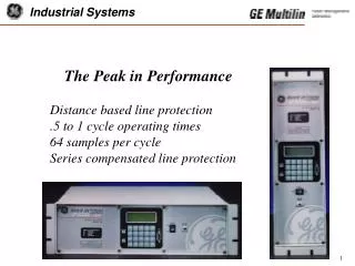
Transmission Lines • A Vital Part of the Power System: • Provide path to transfer power between generation and load • Operate at voltage levels from 69kV to 765kV • Deregulated markets, economic, environmental requirements have pushed utilities to operate transmission lines close to their limits.
Transmission Lines • Classification of line length depends on: • Source-to-line Impedance Ratio (SIR), and • Nominal voltage • Length considerations: • Short Lines: SIR > 4 • Medium Lines: 0.5 < SIR < 4 • Long Lines: SIR < 0.5
Typical Protection SchemesShort Lines • Current differential • Phase comparison • Permissive Overreach Transfer Trip (POTT) • Directional Comparison Blocking (DCB)
Typical Protection SchemesMedium Lines • Phase comparison • Directional Comparison Blocking (DCB) • Permissive Underreach Transfer Trip (PUTT) • Permissive Overreach Transfer Trip (POTT) • Unblocking • Step Distance • Step or coordinated overcurrent • Inverse time overcurrent • Current Differential
Typical Protection SchemesLong Lines • Phase comparison • Directional Comparison Blocking (DCB) • Permissive Underreach Transfer Trip (PUTT) • Permissive Overreach Transfer Trip (POTT) • Unblocking • Step Distance • Step or coordinated overcurrent • Current Differential
IntendedREACH point F1 Z I*Z V=I*ZF I*Z - V RELAY (V,I) What is distance protection? • For internal faults: • IZ – V and V approximately in phase (mho) • IZ – V and IZ approximately in phase (reactance)
F2 IntendedREACH point Z I*Z V=I*ZF I*Z - V RELAY (V,I) What is distance protection? • For external faults: • IZ – V and V approximately out of phase (mho) • IZ – V and IZ approximately out of phase (reactance)
What is distance protection? IntendedREACH point Z RELAY
Voltage at the relay: Source Impedance Ratio, Accuracy & Speed Relay Line System Consider SIR = 0.1
Source Impedance Ratio, Accuracy & Speed Relay System Line Voltage at the relay: Consider SIR = 30
30 20 steady-state output 10 voltage, V 0 -10 -20 -30 0 1 2 3 4 power cycles CVT output Challenges in relay design • Transients: • High frequency • DC offset in currents • CVT transients in voltages
60 40 steady-state output 20 voltage, V 0 -20 -40 -60 0 1 2 3 4 power cycles CVT output Challenges in relay design • Transients: • High frequency • DC offset in currents • CVT transients in voltages
100 50 S POL Reactance comparator [V] 0 -50 S OP -100 -0.5 0 0.5 1 1.5 power cycles Challenges in relay design Sorry… Future (unknown) • In-phase = internal fault • Out-of-phase = external fault
Transient Overreach • Fault current generally contains dc offset in addition to ac power frequency component • Ratio of dc to ac component of current depends on instant in the cycle at which fault occurred • Rate of decay of dc offset depends on system X/R
Zone 1 and CVT Transients • Capacitive Voltage Transformers (CVTs) create certain problems for fast distance relays applied to systems with high Source Impedance Ratios (SIRs): • CVT-induced transient voltage components may assume large magnitudes (up to 30-40%) and last for a comparatively long time (up to about 2 cycles) • 60Hz voltage for faults at the relay reach point may be as low as 3% for a SIR of 30 • the signal may be buried under noise
Zone 1 and CVT Transients • CVT transients can cause distance relays to overreach. Generally, transient overreach may be caused by: • overestimation of the current (the magnitude of the current as measured is larger than its actual value, and consequently, the fault appears closer than it is actually located), • underestimation of the voltage (the magnitude of the voltage as measured is lower than its actual value) • combination of the above
Z1 End Zone Distance Element Fundamentals XL R XC
Impedance locus may pass below the origin of the Z-plane - this would call for a time delay to obtain stability
CVT Transient Overreach Solutions • apply delay (fixed or adaptable) • reduce the reach • adaptive techniques and better filtering algorithms
CVT Transients – Adaptive Solution • Optimize signal filtering: • currents - max 3% error due to the dc component • voltages - max 0.6% error due to CVT transients • Adaptive double-reach approach • filtering alone ensures maximum transient overreach at the level of 1% (for SIRs up to 5) and 20% (for SIRs up to 30) • to reduce the transient overreach even further an adaptive double-reach zone 1 has been implemented
CVT Transients – Adaptive Solution • The outer zone 1: • is fixed at the actual reach • applies certain security delay to cope with CVT transients • The inner zone 1: • has its reach dynamically controlled by the voltage magnitude • is instantaneous
Desirable Distance Relay Attributes • Filters: • Prefiltering of currents to remove dc decaying transients • Limit maximum transient overshoot (below 2%) • Prefiltering of voltages to remove low frequency transients caused by CVTs • Limit transient overreach to less than 5% for an SIR of 30 • Accurate and fast frequency tracking algorithm • Adaptive reach control for faults at reach points
Distance Relay Operating Times 35ms 25ms 30ms 20ms 15ms
Distance Relay Operating Times SLG faults LL faults 3P faults
Relay 4 Relay 3 Relay 2 Relay 1 Actual maximum reach curves
Maximum Torque Angle • Angle at which mho element has maximum reach • Characteristics with smaller MTA will accommodate larger amount of arc resistance
Mho Characteristics Traditional Directional angle “slammed” Directional angle lowered and “slammed” Both MHO and directional angles “slammed” (lens)
Load Swings +XL + = LOOKING INTO LINE normally considered forward Reach Load Trajectory Operate area No Operate area Typical load characteristic impedance +R
Load Swings “Lenticular” Characteristic Load swing
Load Encroachment Characteristic The load encroachment element responds to positive sequence voltage and current and can be used to block phase distance and phase overcurrent elements.
Blinders • Blinders limit the operation of distance relays (quad or mho) to a narrow region that parallels and encompasses the protected line • Applied to long transmission lines, where mho settings are large enough to pick up on maximum load or minor system swings
Quadrilateral Characteristics Ground Resistance (Conductor falls on ground) R Resultant impedance outside of the mho operating region XL
Distance Characteristics - Summary Mho Lenticular Quadrilateral JX R Standard for phase elements Better coverage for ground faults due to resistance added to return path Used for phase elements with long heavily loaded lines heavily loaded
Distance Element Polarization • The following polarization quantities are commonly used in distance relays for determining directionality: • Self-polarized • Memory voltage • Positive sequence voltage • Quadrature voltage • Leading phase voltage
Memory Polarization • Positive-sequence memorized voltage is used for polarizing: • Mho comparator (dynamic, expanding Mho) • Negative-sequence directional comparator (Ground Distance Mho and Quad) • Zero-sequence directional comparator (Ground Distance MHO and QUAD) • Directional comparator (Phase Distance MHO and QUAD) • Memory duration is a common distance settings (all zones, phase and ground, MHO and QUAD)
jX R Memory Polarization Static MHO characteristic (memory not established or expired) ZL Dynamic MHO characteristic for a reverse fault Dynamic MHO characteristic for a forward fault Impedance During Close-up Faults ZS
jX R Memory Polarization Static MHO characteristic (memory not established or expired) ZL Dynamic MHO characteristic for a forward fault RL ZS • Memory Polarization…Improved Resistive Coverage
Choice of Polarization • In order to provide flexibility modern distance relays offer a choice with respect to polarization of ground overcurrent direction functions: • Voltage polarization • Current polarization • Dual polarization
Ground Directional Elements • Pilot-aided schemes using ground mho distance relays have inherently limited fault resistance coverage • Ground directional over current protection using either negative or zero sequence can be a useful supplement to give more coverage for high resistance faults • Directional discrimination based on the ground quantities is fast: • Accurate angular relations between the zero and negative sequence quantities establish very quickly because: • During faults zero and negative-sequence currents and voltages build up from very low values (practically from zero) • The pre-fault values do not bias the developing fault components in any direction
Distance Schemes Non-Pilot Aided Schemes (Step Distance) Pilot Aided Schemes Communication between Distance relays No Communication between Distance Relays
Step Distance Schemes • Zone 1: • Trips with no intentional time delay • Underreaches to avoid unnecessary operation for faults beyond remote terminal • Typical reach setting range 80-90% of ZL • Zone 2: • Set to protect remainder of line • Overreaches into adjacent line/equipment • Minimum reach setting 120% of ZL • Typically time delayed by 15-30 cycles • Zone 3: • Remote backup for relay/station failures at remote terminal • Reaches beyond Z2, load encroachment a consideration
Step Distance Schemes Local Z1 BUS BUS Z1 Remote
Step Distance Schemes Local End Zone Z1 BUS BUS Z1 End Zone Remote
Step Distance Schemes Local Z1 Breaker Tripped BUS BUS Breaker Closed Z1 Remote
Step Distance Schemes Local Z2 (time delayed) Z1 BUS BUS Z1 Z2 (time delayed) Remote
Step Distance Schemes … Z3 (remote backup) Z2 (time delayed) Z1 BUS BUS