Download
1 / 52
570 likes | 1.46k Views
Explore the principles and applications of sputtering in PVD processes for film deposition and etching. Learn about plasma creation, DC sputtering, gas conditions, and surface interactions. References to key publications included.

E N D
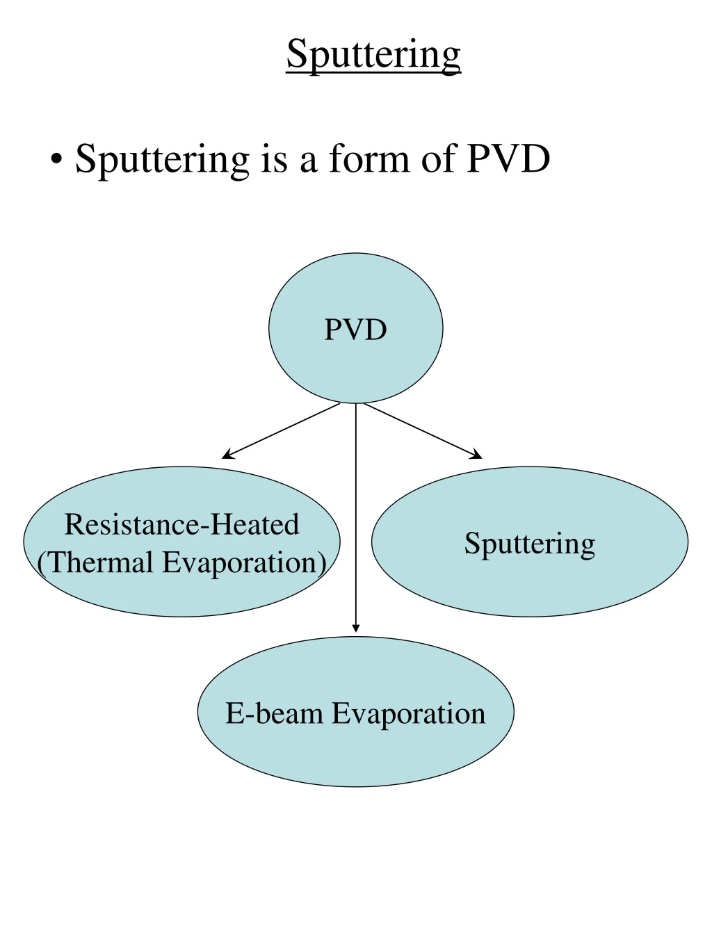
Sputtering • Sputtering is a form of PVD PVD Resistance-Heated (Thermal Evaporation) Sputtering E-beam Evaporation
Sputtering References R.A. Powell and S. Rossnagel, “PVD for Microelectronics: Sputter Deposition Applied to Semiconductor Manufacturing” (Academic Press, 1999) D.M. Manos and D.L. Flamm, “Plasma Etching: An Introduction” (Academic Press, 1989) W.N.G. Hitchon, “Plasma Processes for Semiconductor Fabrication” (Cambridge University Press, 1999) J.L. Vossen and W. Kern, “Thin Film Processes” (Academic Press, 1991) M. Konuma, “Film Deposition by Plasma Techniques” (Springer-Verlag, 1992) D.M. Dobkin and M.K. Zuraw, “Principles of Chemical Vapour Deposition” (Kluwer Academic Publishers, 2003) J.E. Mahan, “Physical Vapour Deposition of Thin Films” (John-Wiley & Sons, 2000) M. Ohring, “The Materials Science of Thin Films” (Academic Press, 1992)
Sputtering Process • A target is bombarded with inert energetic ions, typically Ar+ • Atoms at the surface of the target are knocked loose by a collision cascade process analogous to atomic billiards sputtered atom incident ion
Sputtering Yield Atoms are sputtered from the target with a certain probability, Y, called the sputtering yield Y = # sputtered (ejected) target atoms # incident ions [Y] = atoms/ion
Sputtering Yield Typical sputtering yields are between 0.1 and 4 From Ohring, Table 3-4, p. 113
Sputtering for Film Deposition • The sputtered atoms may be deposited (condensed) on a substrate surface for film deposition Target = source material Substrate for film deposition
Sputtering for Etching • A sample can be placed on the target for etching (plasma-etching, dry-etching, reactive ion etching) Target = sample to be etched
Sputtering • A plasma is used as the source of ions • Other plasma-related processes: PE-CVD, SIMS modified from Mahan, Fig. VII.1, p. 200
Sputtering • There exist different means of creating the plasma Sputtering DC RF Magnetron Sputtering Microwave (ECR)
DC Sputtering: Gas Conditions • A gas is admitted into a chamber filling the space between two electrodes • Typically an inert gas is used like Ar, Ne, Kr, and Xe • Ar is most commonly used • The gas pressure ~ 0.1 – 1 Torr from Mahan, Fig. VI.2, p. 155
DC Sputtering: Anode/Cathode • To create a plasma, a dc voltage • (~ 100’s to 1000’s Volts) is applied between two electrodes • Cathode-anode separation ~ few cm’s) • The cathode is negatively biased and attracts positive ions from the plasma from Mahan, Fig. VI.2, p. 155
DC Sputtering etching deposition from Vossen (1991), Fig. 7, p. 24
Plasma Creation electrons ions anode cathode - + photoemission ionization • Cosmic rays or uv light causes photoemission from the cathode and ionization of the neutral gas atoms
Plasma Creation anode cathode - + • Electrons are accelerated toward the anode • Ions are accelerated toward the cathode • current flow
Plasma Creation anode cathode - + • Electrons may collide with neutral gas atoms causing ionization
Plasma Creation anode cathode - + • Ions striking the cathode produce secondary electrons
Plasma Creation anode cathode - + • Secondary electrons accelerate toward anode and collide with gas atoms causing ionization • e- + Ar Ar+ + 2e-
Plasma Creation anode cathode - + • A multiplication process occurs forming a plasma • This is known as breakdown
I-V Characteristic from Mahan, Fig. VI.14, p. 185 • Ohmic Region • Cosmic rays or uv light causes photoemission of the cathode or ionization of the neutral gas atoms
I-V Characteristic from Mahan, Fig. VI.14, p. 185 • Saturation Region (Region A) • All the available free electrons are collected at the anode as quickly as they are created • I = constant
I-V Characteristic • Townsend Discharge (Region B) • The electrons are accelerated to sufficient energy to cause ionization of the neutral gas atoms from Mahan, Fig. VI.14, p. 185
I-V Characteristic • Breakdown (Region C) • Secondary electron emission produces multiplication process from Mahan, Fig. VI.14, p. 185
I-V Characteristic • Normal Glow (Region D) • Plasma is created near edges of cathode where E-field is highest • The current increases at constant voltage as the plasma extends over the entire cathode surface from Mahan, Fig. VI.14, p. 185
I-V Characteristic • Abnormal Glow (Region E) • Plasma is now extended across entire cathode surface • For further increases in current, the dc applied voltage must increase • This is the region where most sputtering processes occur since it gives the highest sputtering rate from Mahan, Fig. VI.14, p. 185
I-V Characteristic • Arc (Region F) • If the current is increased further, the cathode becomes heated which will either melt or, if the cathode material is refractory, will result in thermionic emission of electrons from Mahan, Fig. VI.14, p. 185
Collisions • 2 ways for plasma particles (electrons, ions) to interact and lose energy Collisions Elastic Inelastic
Elastic Collisions • Elastic collision : • Conserves energy and momentum • Does not result in any internal excitations of the gas atoms or molecules (e.g., vibration, rotation, electronic) M0, E0 Before collision Mr Mr, Er After collision Recoil angle, q M0, E0
Elastic Collisions Mr, Er M0, E0 Recoil angle, q Mr • Conservation of energy and momentum • derive Er (M0, Mr, E0, q)
Elastic Collisions Mr, Er M0, E0 Recoil angle, q Mr Er = 4 E0 M0Mrcos2q/(M0+Mr)2 M0 = mass of incident particle Mr = mass of struck particle initially assumed to be stationary E0 = energy of incident particle Er = energy of recoiling particle (Mr) initially assumed to be stationary q = recoil angle
Heavy Particle Collisions Er = 4 E0 M0Mrcos2q/(M0+Mr)2 • For collisions among ions and neutrals in the plasma, M0 ~ Mr • Er = E0 cos2q • Energy transfer is efficient among ions and neutrals • Ions and neutrals will “thermalize” to the same temperature
Elastic Collisions • The ions do not acquire kinetic energy from the applied field as readily as do the electrons • v = mE • mobility, m = et/m • mi >> me • Typical ion or neutral atom energies are 0.03 – 0.1 eV (300-1000 K) • Ions & neutrals have insufficient energy to cause ionization in the gas • So where do the ions come from ?
Light-Heavy Collisions electron M0, E0 Mr, Er q neutral gas particle Mr • For an electron-gas atom collision: • M0 << Mr • Therefore, • Er ~ 4 E0 (M0/Mr) cos2q
Elastic Collisions • Er ~ 4 E0 (M0/Mr) cos2q • The electron will transfer a maximum energy of • Er = 4 (M0/Mr) E0 • e.g., for an electron colliding with an Ar atom, Er/E0 < 1.4 x 10⁻⁴ • Very little energy is transferred in an elastic collision from the electron to the ions or neutrals in the plasma
Elastic Collisions • But electrons acquire a much higher kinetic energy (and temperature) from the applied field compared to the ions or neutrals due to their much smaller mass • Typical electron energy is 1-10 eV (10000-100000 K) • Recall that typical ion or neutral atom energies are 0.03 – 0.1 eV (300-1000 K) • Electron and ion temperatures are not equal (not in thermodynamic equilibrium)
Elastic Collisions • Electrons and ions/neutrals may each be described by a separate M-B distribution each with their own temperatures, Te and Ti from Manos, Fig. 13, p. 206
Inelastic Collisions • Ions have insufficient energy to cause ionization in the gas • Very little energy is transferred in an elastic collision from electrons to the ions or neutrals in the plasma • Inelastic collisions must be responsible for producing the plasma
Inelastic Collisions Mr, Er, DU M0, E0 q Mr • For inelastic collisions : • DU = E0Mrcos2q / (M0 + Mr) • DU = change in internal energy of the struck particle (vibrational, rotational, electronic excitations)
Inelastic Collisions DU / E0 = Mrcos2q / (M0 + Mr) • For an inelastic collision between an electron and a neutral, M0 << Mr: • DU = E0cos2q
Inelastic Collisions • DU = E0cos2q • DU ~ E0 for forward scattering (q = 0) • Practically all of the electron energy can be imparted to the atom or ion in an inelastic collision
Inelastic Collisions • The energy transfer may vary from less than 0.1 eV (for rotational excitation of molecules) to more than 10 eV (for ionization) from Dunlap, Fig. 8.3, p. 194
Townsend Discharge • As the voltage is increased, electrons may gain sufficient energy from the applied field to ionize a gas atom in an inelastic collision : • e- + Ar Ar+ + 2e- • At this point, ions are created for the first time (Townsend discharge) from Mahan, Fig. VI.14, p. 185
Townsend Discharge • The electron energy must exceed the ionization energy of the gas atoms
Townsend Discharge • Typical ionization energies (10-15 eV) are greater than the mean electron energy (1-10 eV) • Therefore, only electrons in the high energy tail of the M-B distribution will contribute to ionization from Manos, Fig. 13, p. 206
Paschen Curve • The breakdown voltage required to form the plasma is described by the Paschen curve • The minimum in the Paschen curve is around 1 Torr-cm from Powell, Fig. 3.2, p. 53
Paschen Curve • Low pressure or small anode-cathode spacing: electrons can undergo only a small number of collisions in traversing the applied field; not enough ionizing collisions take place to sustain the plasma; a larger voltage is required to sustain the plasma from Powell, Fig. 3.2, p. 53
Paschen Curve • High pressure: mean free path of electrons is reduced; electrons cannot gain sufficient acceleration (i.e., sufficient energy) between collisions to cause ionization from Powell, Fig. 3.2, p. 53
Paschen Curve • Due to the differences in ionization energy and ionization cross-sections for different gases, the Paschen curve will have slightly different shapes for different gases from Konuma, Fig. 3.1, p. 50
Typical dc Plasma Characteristics • Plasma species • Neutral atoms (or molecules depending on the gas), ions, electrons, radicals, and excited atoms • Plasma density • ni = ne ~ 108-1010 cm-3 • nn ~ 3x1015 cm-3 • Degree of ionization • ni, ne << nn • ne / nn ~ 10-5 • Plasma temperature • Te ~ 10000-100000 K (1 – 10 eV) • Ti , Tn ~ 300-1000 K (0.03 – 0.1 eV)
Typical Plasma Characteristics LD from Manos, Fig. 3, p. 191
“Cold” Plasma • Plasma temperature • Te ~ 10000-100000 K (1 – 10 eV) • Ti , Tn ~ 300-1000 K (0.03 – 0.1 eV) • Te >> Ti, Tn but ne, ni << nn • The plasma is essentially at the neutral gas temperature which is quite low • “cold” plasma