Download
1 / 17
200 likes | 307 Views
Electroluminescence Displays. Fakultät für Elektrotechnik und Informationstechnik Lehrstuhl für Kommunikationstechnik Prof. Dr.-Ing. Rüdiger Kays. Jens Bömer jcbsystems@gmx.de. Electroluminescence: Basics & Technology. Introduction Principles of Electroluminescence (EL) general effect

E N D
Electroluminescence Displays Fakultät für Elektrotechnik und Informationstechnik Lehrstuhl für Kommunikationstechnik Prof. Dr.-Ing. Rüdiger Kays Jens Bömer jcbsystems@gmx.de
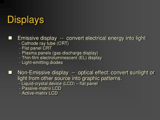
Electroluminescence: Basics & Technology • Introduction • Principles of Electroluminescence (EL) • general effect • high-field EL • Technological Realization • layer structure • Selected Approaches to • produce colours • make a display • Applications/ Products • Pros & Cons Table of Contents
Motivating Forces • tendency to miniaturizement • fast response for video services • low power consumption Introduction
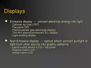
Electroluminescence High Field EL LED & OLED non-thermal conversionof electrical energy into light • pn-junction • electron-hole pair recombination • phosphorus material • hot-electrons • impact excitation Introduction
E2 Luminescence E E1 Fluorescencet 1s Phosphorescencet 1min - ... Eg E0 • Requirements • band gap (Eg) higher than 3.0eV • special semiconductor • insulator • electrical energy is converted into light energy • operation at low temperatures possible Principles of EL
Electron transport Al • insulator/ phosphor interface states • electrons tunnel into phosphor • electrons accelerated by electric field (high energy or “hot” electrons > 2 eV) e- ... topinsulator excited state ITO bottominsulator Excitation • collisions with lattice/ ímpurity atoms (e.g. Mn) • luminescent impurity absorbs electron‘s energy • excited impurity relaxes by emitting a photon impurityground state High Field EL Principles of EL
electrode AC phosphor ( 600nm) insulator( 250nm) T • insulator/phosphor/insulator stack • insulators limit short current • electric field strength > 1.5 MV/cm • 165 V alternating voltage • thin film EL (TFEL) • wide viewing angle • luminosity controlled by pulse width modulation Technological Realization
Red • ZnS:Mn • organic red filter Green • ZnS:TbOF • SrS:Ce Blue • SrS:Ce • SrS:Cu,Ag Amber • ZnS:Mn rare earth oxidsand oxysulfats(as in CRT) White • stacked layers • SrS:Ce and ZnS:Mn Colourful Materials
Luminance (max.) • red: 70 cd/m2 • green 160 cd/m2 • blue: 100 cd/m2 • white: 470 cd/m2 Efficiency • red: 0.8 lm/W • green: 1.0 lm/W • blue: 0.2 lm/W operating temperature-30° C to 65°C Facts Concerning Colours
LCD: thin film EL Contrast ratio Luminance Viewing angle Power consumption 18:1-150:1 200 cd/m2 100°(recently up to 170°) 20W 150:1 150 cd/m2 > 160° 3W Comparison of EL and LCD
One approach: “Colour by White“ • broad band “white“ phosphor • patterned colour filter • indium-tin oxide (ITO) top electrode • pixel size of 12 or 24 micron simple device fabrication low-cost production Selected Approach to Produce Colors
high integration level • low capacity • less current • reduction of control wires fast response Active Matrix (AMEL)Display Organization EL pixel ITO data line Technological advantages column drivers line drivers Selected Approach to Make a Display
b t • Silicon On Insulator (SOI): • Required isolation between high voltage AC of EL deviceand low voltage digital signals which address each pixel. Technological features Advantages of AMEL • aging characteristics of the phosphor • inverted structure • brightness controlled by pulse width modulation • high resolution (2000 lpi) • reduced power consumption • higher brightness • expanded grayscal capability Selected Approach to Make a Display
instrument panels head-up displays (HUD) What is ACTFEL? ACTFEL: alternating current thin film electroluminescence • transparent • minimize driver‘s eye movement • visibility under sunlight • pixel luminance: • amber: 1200 cd/m2 • green: 500 cd/m2 • used in cars • high reliability • wide temperature range • luminance: • red: 23 cd/m2 • amber: 140 cd/m2 • green: 25 cd/m2 Applications
Products EL foil EL display camcorder car control panel(ACTFEL) head mounteddisplay Products
PRO CONTRA • high resolution • fast response • low power consumption • wide viewing angle • ruggedness • low-cost production • use at low temperatures • visibility under sunlight • inadequate brightness and chromaticity • aging characteristics • high voltage • alternating current Pros and Cons
HFEL bases on high energy electrons (hot electrons) • Self-emitting technology instead of light through (LCD) • Realization with an insulator/phosphor/insulator stack • Multi-colour displays by “white phosphor“ and colour filters • Various monochrome control panels by variation of dopants • Active matrix integration (AMEL) • Application in cars, laptops, head-mounted-displays, camcorder Summary