Download
1 / 15
150 likes | 266 Views
FM Transmitter. Matt Baker Kevin Van Dyke. Design. Three stage, 9V FM transmitter Audio amplification Oscillation RF amplification Electret microphone for input Dipole antenna – 160 cm. Circuit Diagram. Circuit Description. Radio frequency oscillator (100MHz)

E N D
FM Transmitter Matt Baker Kevin Van Dyke
Design • Three stage, 9V FM transmitter • Audio amplification • Oscillation • RF amplification • Electret microphone for input • Dipole antenna – 160 cm
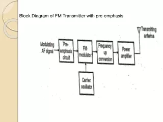
Circuit Description • Radio frequency oscillator (100MHz) • Microphone picks up and amplifies audio and then feeds it to first transistor for amplification • Output from collector is fed into base of the second transistor where it modulates the resonant frequency of the tank circuit • This is done by varying the junction capacitance of the transistor. • Junction capacitance is a function of the potential difference applied to the base of the second transistor.
Oscillation occurs • Final stage: Third transistor amplifies the output RF signal.
Electret Microphone • What is an electret? • It is a permanently charged dialectric. • The diaphragm of the microphone acts as one of the plates in the capacitor. • The movement of the plate changes the capacitance. • Amplified by a FET amplifier.
First amplification stage • Standard self-biasing common emitter amplifier • The 22n capacitor isolates the microphone from the base voltage of the transmitter by blocking DC.
Oscillator necessary to generate RF carrier waves Feedback signal makes the base-emitter current vary at the resonant frequency. This causes the emitter-collector current to vary at the same frequency. This signal then radiated as radio waves. Oscillator Stage
This stage amplifies the RF signal. A Zetex ZTX320 RF transistor was used to do this efficiently. L2 and the 10p capacitor in parallel with it are designed to reduce harmonics from the circuit. Output power from this stage will be maximum when it is tuned to oscillate at the same frequency as the previous stage. How? Peaking Circuit Final Amplification Stage
Uses diodes to charge a capacitor. Measure voltage across cap w/ voltmeter. To tune circuit, move turns of coil L3 further apart or closer together until the reading on the voltmeter is maximum. Peaking Circuit