Download
1 / 41
420 likes | 467 Views
FM Transmitter. Dec06-01. Team: Grant Blythe Tony Hunziker Luke Erichsen. Advisors: Dr. John W. Lamont Prof. Ralph E. Patterson III. Client: Iowa State University - Senior Design. Date: December 5, 2006. Presentation Outline. Introduction Introductory Material Project Activities

E N D
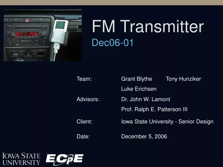
FM Transmitter Dec06-01 Team: Grant Blythe Tony Hunziker Luke Erichsen Advisors: Dr. John W. Lamont Prof. Ralph E. Patterson III Client: Iowa State University - Senior Design Date: December 5, 2006
Presentation Outline • Introduction • Introductory Material • Project Activities • Design • Implementation • Resources and Schedules • Conclusion
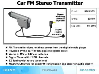
Project Overview Objective: Design a portable short range FM transmitter for use with MP3 players or satellite radios
Definitions FCC: FM: LCD: MP3 player: PLL: RF: Transmission frequency: VCO: Federal Communications Commission frequency modulation, a method of modulating an audio signal for wireless transmission liquid crystal display portable digital music player, (i.e. ipod) phase-lock loop radio frequency the frequency at which the device is transmitting the FM modulated signal to the FM radio voltage controlled oscillator
Acknowledgement The team would like to thank the following people for their help and support. Jason Boyd: For showing us various possibilities for prototyping surface mount components. Dr. John W. Lamont and Prof. Ralph E. Patterson III: For your knowledge and guidance in helping us with part selection and referring us to expert advice when needed. Dr Geiger: For help understanding the phase lock loop Fredo: For a helpful reference. Yesuratnam Thommandru: For help uderstanding programming PIC’s
Problem Statement General Problem Statement: Currently many people use MP3 players and satellite radios, but do not have a way to connect them to their other audio equipment. It should be easily tunable to transmit on any desired frequency in the FM band (88-108 MHz) with the ability to preset four selectable frequencies within this range. The minimum transmission distance is to be at least twelve feet. General Solution Approach: Most of this existing equipment has FM radio capabilities, so the solution approach was to develop a portable FM transmitter to link MP3 players and satellite radios to any FM receiver.
Operating Environment • The finished device will operate within a personal vehicle or a household room that could be exposed to: • Moisture • Dust/Dirt • Impacts • Temperatures from 32° - 100° F • Normal humidity/pressure
Intended Users/Uses Intended Users: The intended user for this product is anyone owning a MP3 player or satellite radio device. Intended Uses: The FM transmitter is intended to make personal music devices accessible through home and car stereos.
Assumptions • The device will receive a 20 Hz to 20 kHz input audio signal from all varieties of personal music devices. • The device will output to standard North American FM radio equipment. • The transmitter will be subjected to a variety of environments including varying temperatures, humidity, vibration levels, and electromagnetic noise. • The device will be operated in varying ambient light conditions. • The user will have access to a steady power source.
Limitations • The cost to purchase this product shall not become uncompetitive. • The transmitter must conform to FCC regulations. • Part 15 concerning unlicensed FM broadcasting • Broadcast strength: ≤ 0.1W • Broadcast band: 88 -108 MHz • The device shall be capable of obtaining power from readily available power sources. • The size shall not exceed 6 in. by 6 in. by 3 in. • The weight shall not exceed 1 lb.
Expected End Product • The device case will be made of plastic • The case will allow for easy hand manipulation and transportation • The device will implement an LCD screen displaying the transmission frequency. • The device will be accompanied by a user manual. • The user input interface will consist of six buttons. • “up” and a “down” button to adjust transmission frequency • 4 buttons will each access a programmable preset frequency • Transmit a minimum of 12 ft
Present Accomplishments Problem Defined Successfully completed Research Completed Successfully completed Technologies Selected Successfully completed Design Completed Successfully completed Design prototyped Completed Prototype testing Partially completed Project documented Successfully completed
Approaches Considered Logic Approach The logic for the transmitter could be implemented either with a microcontroller and software or with dedicated hardware logic.
Approaches Considered Display Approach Due to self-imposed assumptions, transflective LCD’s were only considered. Transflective LCD’s allow data to be viewed with and without a backlight.
Approaches Considered Programming Approach It was possible to program the PIC in two different languages. The two different languages were Assembly or C.
Project Definition A successful project will result in a device that: • shall receive an input signal and broadcast it on the FM band • shall receive its signal input from a 3.5mm input port • shall accept power from a cigarette lighter/power socket of an automobile or a standard wall outlet • shall be capable of storing 4 programmable transmission frequencies • shall display the transmission frequency on a back-lit display
Research Activities FM Radio Transmission • Uses transmission band of 88-108 MHz • Signal Modulated onto carrier frequency • Backwards compatible with stereo/mono
Research Activities FCC Rules • Part 15 concerning unlicensed FM broadcasting • Broadcast strength: ≤ 0.1 W • Broadcast band: 88 -108 MHz LCD Displays • Reflective technology • Transflective technology • Backlights
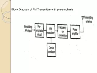
Design Activities Functional Diagram • Inputs • Processing • Outputs
Design Activities Microcontroller • PIC 16F877 • 28 Pin DIP • Non-Volatile Memory • I/O Handles all device logic • Controls user interface • Data connection to signal processor, LCD display • Controls backlighting
Design Activities Signal Processor • Rohm BH1415F • SOP22 • Phase Locked Loop • Stereo Capability • Built in pilot tone • Serial communication with microcontroller
Design Activities Overall Schematic
Design Activities Component Communication • Serial Connection from microcontroller to signal processor
Design Activities Component Communication For Example: in the case of 99.7 MHz carrier frequency. 99.7 MHz / 100 kHz (fref) = 997 3E5 (HEX)
Implementation Activities Changes From Original Design • LCD display • Switched to VI – 415 from VIM – 404 because of ease of connecting to PIC. • Clock • Switched from a clock to a ceramic resonator. • Serial connection • Used output pin instead of serial connection.
Implementation Activities Problems • PIC • Problems getting compilers installed and working in senior design labs. Solved by downloading free compiler online and bugging the Computer Support Group. • Problems getting PIC to work. Initial registers were not initialized. Once watchdog timer, code-protection, and low – voltage program were disabled and the clock type was selected, PIC worked. • Transmitter Circuit • Problems getting the output signal. Solved by enabling the transmitter chip.
Implementation Activities How Implementation Process Can Be Improved • Make sure all necessary programs were installed before needed. • Read all documentation on device. • Schedule extra time for delays
Testing/Modification Device Subsystem Testing • Testing of signal modulation • Test composite signal generation • Test RF oscillator • Test output power • Transmission occurs across frequency band • Power system tested for reliability • Control system tested for proper function Prototype Testing • Integration of all subsystems • Verifying prototype meets or exceeds all design requirements • User testing • Advisor/Client acceptance testing
Testing/Modification Results Device Subsystem Testing Results • Testing of signal modulation • Composite signal generates successfully • RF voltage controlled oscillator does not initialize • Testing output power • Output ≈ .085 W which is less than FCC broadcast strength of .1 W • Control system tested for proper function • I/O control works successfully Prototype Testing Results • Integration of all subsystems • Verifying prototype meets or exceeds all design requirements • RF VCO failure causes transmission system failure • Advisor/Client acceptance testing • Not completed
Resources Personnel Efforts • 4 Team members first semester • 3 Team members second semester • Jacob Sloat studying abroad
Resources Project Finances
Resources Project Schedule
Project Evaluation Milestone Evaluation Criteria
Project Evaluation Previously defined passing score = 80%
Commercialization / Additional Work Commercialization • Product market already exists • Several competitors established in market • Will be difficult to establish in market • Must provide unique features to compete Recommendations for Additional Work • Commercialization of product • Expanded functionality • Auto-Seek frequency to broadcast on • Multiple input sources • HD radio output
Lessons Learned What went well? • Team member interaction • Programming (after initial configuration error) • Documentation What did not go well? • Configuring PIC programmer • Transmission circuit debugging • Device implementation
Lessons Learned Knowledge gained • FM modulation process • Microcontroller programming • LCD display drivers • Soldering skills What would we change? • Make sure necessary programs were installed before needed • Talk to someone with background in RF • Have a computer engineer on the team • Project schedule
Risk Management Anticipated Potential Risks Risk: Loss of a team member Management: Increase remaining members efforts Risk: Component Failure Management: Ordered multiples of the less common components Risk: Delay Receiving Parts Management: Rescheduling of tasks
Risk Management Encountered Risk - Anticipated Loss of a team member: Successfully managed through increased efforts Delay receiving parts: Successfully managed through task rescheduling Component failure: Ordered extra parts Encountered Risk - Unanticipated Complexity of technology: Marginally managed with additional research
Summary The FM Transmitter project was meant to create a device that allowed the output of a personal music device to be utilized by a car or home stereo. While a fully functional device was not sucessfullly implemented, the groups technical knowledge was expanded and its project management skills refined.