Download
1 / 30
310 likes | 369 Views
Design of Highway Vertical Alignment Chapter 16. Dr. TALEB M. AL-ROUSAN. Introduction. The vertical and the horizontal layout of the highway make up the alignment. The design of alignment depends primarily on the design speed selected for the highway.

E N D
Design of Highway Vertical AlignmentChapter 16 Dr. TALEB M. AL-ROUSAN
Introduction • The vertical and the horizontal layout of the highway make up the alignment. • The design of alignment depends primarily on the design speed selected for the highway. • The least cost alignment is one that generally takes the form of the natural topography. • Often this is not possible, because designer has to adhere to certain standards that may not exist on the natural topography. • Its important that the alignment has consistent standards to avoid sudden changes in the vertical and horizontal layout of the highway.
Introduction Cont. • Horizontal and vertical alignment should be designed to complement each other for safe and more attractive highways. • Proper balancing of the grades of tangents with curvatures of horizontal curves and the location of horizontal and vertical curves with respect to each other. • Example on poor design: sharp horizontal curves placed at or near the top of crest curve or bottom of sag curve will create hazardous section of the highway.
Vertical Alignment • Consists of straight sections of the highway known as grades, or tangents connected by vertical curves. • The design of vertical alignment involves selection of suitable grades for the tangent sections and the design of the vertical curves. • Topography of the area which the road traverses has a significant impact on the design of the vertical alignment.
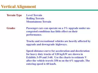
Vertical Alignment/ Grades • Grades affect the performance of vehicles (reduce speed) specially for trucks. • Max grades on highways should be selected to limit grade effect on vehicle performance. • Selection of max grade depends on • Design speed. • Design vehicle • 4-5% grades have little or no effect on PC. • Studies showed that speeds may increase up to 5% on downgrades and decrease by 7% on upgrades depending on percent and length of grade.
Vertical Alignment/ Grades • Maximum grades have been established, based on operating characteristics of design vehicle. • Max grade vary from 5% for DS of 70 mi/h to 12% for DS of 30 mi/h. • See Table 16.4 for recommended values of max grades. • Max grades in the Table should not be used frequently, particularly when grades are long and traffic include high % of trucks. • on low volume rural highways, maximum grades may be increase by 2% When : • grade length (< 500 ft) and • roads are one-way in the downgrade direction,
Vertical Alignment/ Grades • Minimum grades depend on the drainage condition of the highway. • 0% grades may be used on uncurbed pavements with adequate cross-slopes to laterally drain the surface water. • When pavements are curbed, longitudinal flow should be provided to facilitate the longitudinal flow of surface water. • Min of (0.5%).
Vertical Curves • Used to provide gradual change from one tangent grade to another so that vehicle may run smoothly as they traverse the highway. • Usually parabolic in shape • Classes or types (see Figure 16.11) • Crest vertical curves • Sag vertical curves • Main criteria for design are: • Provision of min stopping sight distance (associated with crest vertical curves only) • Adequate drainage • Comfortable in operation • Pleasant appearance • All four criteria are associated with sag vertical curves.
Crest Vertical Curves • Conditions for min length: • When sight distance > length of curve. • When sight distance < length of curve. • For the first condition (see Figure 16.12) • For second condition (see Figure 16.13)
Crest Vertical Curves When (S > L) L min = 2S –[(200 (SQR(H1) + SQR(H2))2/ A] L: length of vertical curve (ft) S: sight distance (ft) = SSD = 1.47 u t + [u2 / (30 [(a/g) ± G)])] H1: height of eye above road surface = 3.5 ft H2: height of object above road = 2.0 ft G1: Slope of first tangent G2: Slope of second tangent A : grades algebraic difference = Abs [G1 – G2] PVC: Point of vertical curve PVI :Point of vertical intersection PVT: Point of vertical tangent L min = 2S – [2158/A]For (S>L)
Crest Vertical Curves When (S < L) L min = (A S2)/[(200 ((SQR(H1) + SQR(H2))2] L: length of vertical curve (ft) S: sight distance (ft) = SSD = 1.47 u t + [u2 / (30 [(a/g) ± G)])] H1: height of eye above road surface = 3.5 ft H2: height of object above road = 2.0 ft G1: Slope of first tangent G2: Slope of second tangent A : grades algebraic difference = Abs [G1 – G2] PVC: Point of vertical curve PVI :Point of vertical intersection PVT: Point of vertical tangent L min = (A S2)/2158For (S< L)
Sag Vertical Curves • Selection of min. length of sag vertical curve is controlled by: • Sight distance provided by the headlight. • Rider comfort • Control of drainage • General appearance • see Figure 16.14) for headlight sight distance on sag vertical curve with (S>L).
Sag Vertical Curves Min. Length When S > L L min = 2S –[(200 (H1 + S tan β)/ A] H= height of headlight = 2 ft (β) is angle of upward inclination of the headlight beam = 1o L min = 2S –[(400 + 3.5 S)/ A] for (S>L) When S < L L min = (A S2)/[(200 (H + S tan β] L min = (A S2)/(400 + 3.5 S] for (S<L)
Sag Vertical Curves Cont. • To provide safe conditions on a sag curve, the length of curve must be such that the light beam sight distance (S) be at least equal to the SSD. • The comfort criterion for the design of sag curves require that both gravitational and centrifugal forces act in combination . • Comfortable ride will be provided if the radial acceleration is not greater than 1 ft/sec2. L min/ comfort = (A U2) / 46.5 U: design speed in mi/h
Sag Vertical Curves Cont. • The drainage criterion for sag curves is essential when the road is curbed. • Maximum length is given here rather than min. • To satisfy drainage criterion a min. grade of (0.35%) be provided within (50 ft) of the level point of the curve. • Max length > min. lengths for other criteria for speeds up to 60 mph and = min. length for a 70 mph. • The criterion of general appearance is satisfied by: L min /appearance = 100 A
Elevation of Crest Vertical Curves L min = 2S – [2158/A]For (S>L) L min = (A S2)/2158For (S< L) when S< L, L min can be rewritten as: L min = KA For (S< L) K = length of vertical curve per percent change in A. K= rate of vertical curvature • SeeTable 16.5for design controls of crest vertical curves. • It has been found that when S> L, L min can are not practical design values and generally not used. • General practice for the S>L case is to: • set min. limits ranging from (100 – 325 ft) or • min length can be set at (3 times) design speed.
Elevation of Crest Vertical Curves Cont. • After determining the length of the crest vertical curve. • The elevation of the curve at regular intervals can then be determined. • Done by considering the properties of the parabola (Y = a X2) • See Fig. 16.15 • Note: in the figure, the length of the vertical curve is the its horizontal projection not the length along the curve • (L = T1 + T2 = 2T)
Elevation of Crest Vertical Curves Cont. • (L = T1 + T2 = 2T) • From properties of a parabola with (Y = a X2), the rate of change of slope (second derivative) = 2a…………. a is constant • If the total change in slope is A, then 2a = A/(100L)… a = [A/ (200 L)] • Curve equation: Y = [A/(200 L)] X2 • When x=L/2 , the external distance (E) from PVI to the curve is found by: E = [A/(200L)](L/2)2 = [AL /800] • Since stations are given in 100 ft intervals E = AN/8…… N= length of the curve in stations. • Any point on the curve can be given in terms of E, by substituting A=800E/L in the curve equation Y = E [X/( L/2)]2
Location of high Point (Turning Point) of Crest Vertical Curves • High point (turning point) is of interest to the designer because of drainage requirements. • Xhigh = distance from BVC to the turning point Xhigh = [(100L)/(G1-G2)](G1/100) Xhigh = [LG1/ (G1-G2)] • Yhigh = difference in elevation between BVC and the turning point. Yhigh = (LG12)/(200(G1-G2))
Procedure for the Design of Crest Vertical Curve • Determine min. length of curve to satisfy sight distance (S>L or S<L). • Determine from layout plans the station and elevation of the PVI. • Compute elevations of the BVC and end of vertical curve EVC. • Compute offsets (Y) from the tangent to the curve at equal distance (100-ft) beginning with the first whole station after the BVC. • Compute elevations on the curve. • See Example 16.4for design of crest vertical curve.
Elevation of Sag Vertical Curves • Same format as crest vertical curves. • The headlight sight distance requirement is used for design purposes since SSDs based on it are generally within limits of accepted values. L min = 2S –[(400 + 3.5 S)/ A] for (S>L) L min = [(A S2)/(400 + 3.5 S)] for (S<L) • See Table 16.7 for design controls of sag curves which are expressed in terms of K (rate of vertical curvature). • Computation of the elevation at different points on the curve takes the same form as for the crest vertical curve. • But, offset (Y) is added to tangent elevation since the curve elevation is higher than the tangent. • See Example 16.5 for design of sag vertical curve.