Download
1 / 16
170 likes | 259 Views
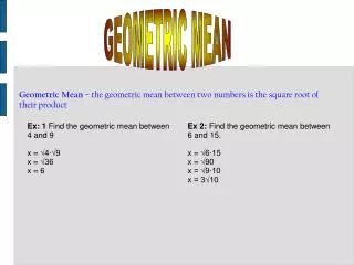
GEOMETRIC DESIGN: VERTICAL ALIGNMENT. CE331 Transportation Engineering. Objectives. Describe components of vertical alignment Understand the design criteria for vertical curve Determine the minimum length of a vertical curve Calculate the stations and elevations along a vertical curve.

E N D
GEOMETRIC DESIGN:VERTICAL ALIGNMENT CE331 Transportation Engineering
Objectives • Describe components of vertical alignment • Understand the design criteria for vertical curve • Determine the minimum length of a vertical curve • Calculate the stations and elevations along a vertical curve
Vertical Alignment • Components • Tangent grade • AASHTO guideline recommends maximum grades • Vertical curve • Minimum length (Lmin) • Stations and elevations of points along the curve
Vertical Curve • Usually parabolas • Crest or sag • Length measured along the horizontal plane
Assistant with Target Rod (2ft object height) Observer with Sighting Rod (3.5 ft)
Design Criteria • Provide minimum Stopping Sight Distance (SSD) • Required at any point • Provide adequate drainage • Provide comfortable ride • Provide pleasant appearance • Natural topography • Environment/views • Horizontal curves • Balance grades
Minimum Length of the Vertical Curve (Lmin) – based on SSD requirement A = |g2 – g1|*100 (%) SSD: Stopping Sight Distance (ft)
Alternate method … Design Values (K) for SSD Rate of curvature K is length per 1% A Example A=5% @ u=80 km/h Lmin= 5(26)=130 m Crest Lmin= 5(30)=150 m Sag
Example • A vertical curve connects a 3% grade with a 0% grade. The required stopping sight distance is 440ft. What should be the minimum length of the curve?
Calculate Stations & Elevations • End points • Sta.PVC = Sta.PVI – L/2 • HPVC = HPVI – g1·L/2 • Sta.PVT = Sta.PVI + L/2 • HPVT = HPVI + g2·L/2 • Other points • Define a coordinate system (next slide) • Find H for each x (usually in 100ft increment)
H PVI g1 g2 Y PVC x PVT x L/2 L/2 Y Vertical Curves HP= HPVC + g1 x + (g2– g1)x2 / 2L
Examples • Two types of design problems • Unconstrained • Constrained • Passing through certain point, or • Maintaining certain clearance from object
250/2 0.03 250 175.20 -0.03-0.03 Example(1/4) Elevation at middle? Sta 1+240.00 Elev. 175.20 +3% -3% 250 m = 177.08 HP= HPVC + g1 x + (g2– g1) x2 / 2L
1400-1240 0.03 250 175.20 -0.03-0.03 Example(2/4) Min clearance 4.5 m? Elev. 180.40 Sta 1+400.00 Sta 1+240.00 Elev. 175.20 +3% -3% 250 m = 176.93 HP= HPVC + g1 x + (g2– g1) x2 / 2L Δ=180.40-176.93 = 3.47 m NO
Elev. Sta L m L/2 35 L/2 + 35 0.03 175.90 -0.03-0.03 178.95-.03(L/2) Example(3/4) L for min clearance 4.5 m? Elev. 180.40 Sta 1+400.00 Sta 1+240.00 Elev. 175.20 PVI Sta 1240+250/2=1+365.00 Elev. 175.2+.03(125) = = 178.95 +3% -3% HP= HPVC + g1 x + (g2– g1) x2 / 2L
Example(4/4) 175.90 = [178.95-0.03(L/2)]+[0.03(L/2+35)]+ +[(-0.03-0.03)(L/2+35)2/2L] 175.90-178.95-0.03(35)= -0.06(L/2+35)2/2L -4.1= -0.06(L/2+35)2/2L 136.67L =(L/2+35)2 136.67L=L2/4+2(L/2)(35)+352 L2-406.67L+4900=0 L1 = 12.43 m L2 =394.24 m