Download
1 / 24
240 likes | 242 Views
This document provides an overview of the status, plans, and needs for TPC electronics, including information on chips, data paths, design, and requirements.

E N D
TPC electronics Status, Plans, Needs Marcus Larwill April. 2007
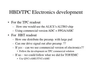
Short list of topics • The Pasa/Altro chips ( have been purchased ) • Mipp TPC data path requirements • Design and layouts of new Sticks • Altro chip specifics intro.
System Overview L1: 6.5ms 1 KHz L2: < 100 ms 200 Hz power consumption < 40 mW / channel Drift Chamber STICK (128 CHANNELS) drift region 16ms Amp ZIF connector 40bit parallel bus Serial interface 8 CHIPS (16 CH / CHIP) 8 CHIPS (16 CH / CHIP) FEC-FPGA Memory gating grid Digital Circuit PASA ADC RAM anode wire ALTRO pad plane 15360 channels CSA SEMI-GAUSS. SHAPER 1 MIP = 4.8 fC S/N = 30 : 1 DYNAMIC = 30 MIP • BASELINE CORR. • TAIL CANCELL. • ZERO SUPPR. 10 BIT < 12 MHz MULTI-EVENT MEMORY GAIN = 12 mV / fC FWHM = 190 ns
Data Path Requirements of TPC • The SY120 program will switch to one 4 second slow spill every 2 minutes. • The drift volume height is 75cm, corresponding to a maximum collection time of 15usec. • The TPC grid is currently limited to a maximum pulse rate of 3kHz. • The readout should be capable of a sustained rate of .3ms per event and a burst rate of .2ms per event. • The 15360 channels of TPC are used to measure particle trajectory momentum and dE/dx. • The detector is currently instrument with 128 analog/digital electronics cards “sticks” which would be designed to have PASA/ALTRO chips. 15360/128=120 • For the TPC there will be 250 samples per event channel to match the drift time of the detector. • With a zero suppressed event size estimated to be 115kb for multi track events.
Data Path of TPC • A 575mb/s burst rate readout could be achieved with 5-way parallel 115mb/s datapaths. • Each PASA/ALTRO chip sets has a 10bit 40MHz. ADC, with digital signal processor and memory buffer. • The chips are controlled over a 40bit wide bus that supports 200MB/s. • The ALTRO event buffer will be able to fully buffer 8 events.
TPC 15360 channels 15us drift time 3kHz maximum readout (300us) 115kbytes est. event 20MHz sample clk Rate into Readout System 115kbytes/300us=383Mbytes/sec 4secx383Mbytes/sec=1532Mbytes/spill 1532M/120=12.8Mbytes/sec 4sec. spill every 120sec. 250bytes/event per ch x 16ch per Pasa-Altro=4000bytes/event 1/300us=.3m max event rate 4000/.3m=13.3Mbytes/sec. per Pasa-Altro 8x13.3Mbytes=106.4Mbytes/sec per Stick PASA 16 channel per PASA 250 samples per channel per event ALTRO 10 bit ADC 20MHz 200MBytes/sec 40bit data path (40MHz. Rclk) Per ALTRO Data Processor 1024x40 ADC Multi event buffer 1024x40 Front end card buffer controller Data Processor ADC Multi event buffer 1024x40 Data Processor ADC Multi event buffer 8 ALTRO per Buffer 1024x40 Data Processor ADC Multi event buffer LV2 Trig LV1 Trig 16 channels per ALTRO 20MHz master clock (sample rate) 8 Pasa-Altros x16 ch each stick = 128 ch per stick (?)# 124 sticks
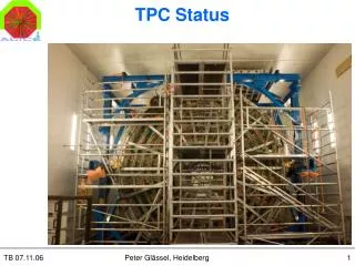
How we compare to E907 Front End Cards (Sticks) The “sticks,” sit in the electronics bay just below the pad plane. The sticks are multi-layer boards mounted on aluminum for cooling. When installed, the base of the stick assembly is in contact with the bottom of the electronics bay, which is water-cooled. There are on-board power and interlock connections. The exhaust passes a smoke detector on the AC interlock loop. The sticks connect to the pad plane through a ZIF card edge connector. The pad plane and ZIF connector, encode the stick slot position and form an interlock for proper card insertion. If the card is not completely inserted, the interlock contacts are not made up, and the DC power supply interlock will not make up for that stick, preventing power from being applied to the board. The sticks also contain a thermal limit switch, set to open at 40°C, in the interlock chain.
Prototype Top level schematic of Altro/Pasa chips on Stick for Mipp
Layout of Stick with Pasa/Altro chip set on main board Layout of Stick with Pasa/Altro chip set on daughter cards
Schematic of Stick front end card buffer logic (Now with transformer coupled LVDS interface)
Schematic of Stick front end card buffer logic FPGA (Now with clock fanout inside FPGA)
Schematic of Stick slow communication processor Interface to front end card buffer logic FPGA
Layout of Stick front end card buffer logic for Pasa/Altro chip set
Block diagram of FPGA code for control logic of Pasa/Altro chip set A simulation has been done using a VERILOG model of the ALTRO chip with code from the Alice front end design. The simulation is working but additions for serial readout and multi event buffering are still being added.
Altro Registers The total number of registers implemented in the ALTRO chip is 137. Out of these 128 are channel specific. That is, a different version exists for each channel. These are 8 channel-specific registers for each of the 16 channels (8x16= 128) The remaining 9 registers contain parameters that are either common for all the channels or relative to the common logic of the chip. The PMD register is not a true register, but a gateway to access the pedestal memories.