Download
1 / 14
140 likes | 334 Views
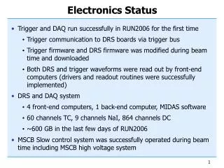
TOTEM ELECTRONICS STATUS. Walter Snoeys. CMS based: APV + optical links for data, trigger and control Trigger electronics TOTEM specific: New trigger chip developed by CERN-MIC (VFAT) provides: 128 channels digital tracking data + 128 deep pipeline memory

E N D
TOTEM ELECTRONICSSTATUS Walter Snoeys Collaboration meeting 25/2/2004
CMS based: APV + optical links for data, trigger and control Trigger electronics TOTEM specific: New trigger chip developed by CERN-MIC (VFAT) provides: 128 channels digital tracking data + 128 deep pipeline memory Serial tracking data output upon trigger signal 8-10 trigger outputs (fast or of group of channels) On trigger plane 4 APV’s replaced by 4 VFAT’s: Trigger outputs grouped over 1 optical serial link/plane Tracking data sent over analog APV link TOTEM trigger box: Receives and synchronizes optical trigger signals Performs trigger generation Sends trigger to CMS and/or TOTEM Detector geometry TOTEM specific: Geometrical redesign of CMS electronics close to detectors Counting room electronics for CMS part identical Roman Pot (and T2) Electronics Collaboration meeting 25/2/2004
Roman Pot electronics Totem APV hybrid Manu Sanchez EST design 1st version ok Totemflex “ 2 wks Totem APV testcard (arcs & st cms compatible) “ 2 wks Production to be organized asap Rui De Oliveira EST VFAT Testcard J. Kaplon + MS EST 2 wks Production to be organized asap Rui De Oliveira VFAT Testing Shayar + Roberto Dinapoli after testcard Totem VFAT hybrid Roberto Dinapoli + MS EST design in April, production go ahead after 1st VFAT measurements Roman Pot Motherboard Lyon input for schematic CMS part Need to define optical Some input on optical link (A. Kok) serial link (800MHz vs 1.6 GHz) + decision on VFAT readout SPS cables and patch panels Anne-Laure Perrot + Daniela Macina cables ordered + installed, patch panels in course of definition SPS trigger signals Marco Bozzo people contacted to obtain clock and trigger signals from Beam Monitor Cooling electronics F. Haug + AL Perrot (patch p) Definition in progress Roman Pot control (motor) M. Oriunno + AL Perrot(“) Use hardware chosen by machine people Roman Pot T & P measurement M. Oriunno(P)+ E. Noschis(T)+ AL Perrot (patch P) Nat. Instr. based for T (Elias), P in progress Roman Pot High Voltage G. Ruggiero Caen based, interface available, needs some work Detector design G. Ruggiero + E. Noschis + V. Eremin + C. Kenney 3D planar in processing, end of March, edgeless design 2 wks Optohybrids A. Kok + group F. Vasey testing & qualifying, GOL link to be defined further FEC electronics Mic Group + Brunel qualifying boards FED electronics Mic Group + Brunel + RAL SPS + X5 trigger box ?? Optical link dependent, needs deserializer + then some concidence Alignment and mounting procedure definition input from Sherwood Parker, Marco O come close to final solution G. Ruggiero, M. Deile Roman Pot and X5 compatible Collaboration meeting 25/2/2004
T2 electronics X5 Test Compass (APV) based Marco Bozzo + ?? Design is there, some production necessary, will watch geometrical compatibility with final system Final system APV and VFAT Marco Bozzo + ?? Similar to (positive answer from Compass: outputs (fast or of group of channels) T2 electronics Totemflex “ 2 wks Totem APV testcard (arcs & st cms compatible) “ 2 wks Production to be organized asap Rui De Oliveira EST VFAT Testcard J. Kaplon + MS EST 2 wks Production to be organized asap Rui De Oliveira Totem APV hybrid Manu Sanchez EST design 1st version ok VFAT Testing Shayar + Roberto Dinapoli after testcard Totem VFAT hybrid Roberto Dinapoli + MS EST design in April, production go ahead after 1st VFAT measurements Roman Pot Motherboard Lyon input for schematic CMS part Need to define optical Some input on optical link (A. Kok) serial link (800MHz vs 1.6 GHz) + decision on VFAT readout SPS cables and patch panels Anne-Laure Perrot + Daniela Macina cables ordered + installed, patch panels in course of definition SPS + X5 trigger box ?? Optical link dependent, needs deserializer + then some concidence SPS trigger signals Marco Bozzo people contacted to obtain clock and trigger signals from Beam Monitor Cooling electronics F. Haug + AL Perrot (patch p) Definition in progress Roman Pot control (motor) M. Oriunno + AL Perrot Use hardware chosen by machine people Roman Pot T & P measurement M. Oriunno(P)+ E. Noschis(T)+ AL Perrot (patch P) Nat. Instr. based for T (Elias), P in progress Roman Pot High Voltage G. Ruggiero Caen based, interface available, needs some work Electronics status Collaboration meeting 25/2/2004
Roman pot mother board Atmospheric side glue Flange vacuum Support arm Connector for flex circuit Flexible connections Alignment marks Spacers and frames Readout chips Printed circuit board Printed circuit board Detector detector beam Collaboration meeting 25/2/2004
LDD LDD LDD Coincidence box CCU Module CCU Module CCU Module CCU Module CCU Module Analog optohybrid patch panel patch panel Roman Pot Trigger system Totem Trigger Box Roman Pot Mother board DAQ Interface Analog optohybrid TTCrx Data Processing 96 FED Analog system Digital optohybrid TTCrx Central Processing RX FEC Digital system Counting Room Radiation environment Collaboration meeting 25/2/2004
This is the card inside the Roman Pot which incorporates the CMS hybrid with 4 APV chips Interconnect to the outside 40 connections at low voltage for hybrid itself 4 connections for Pt-100 2 (Gnd and high voltage) connection => low voltage ZIF kapton connector 51 pin for low voltage and Pt-100 => high voltage minimum two wires Need good thermal connection to frame (TOP and Bottom), needs Cu feedthroughs TOTEMTRACK motherboard flange Tracking conn. Trigger conn. High voltage connector Low voltage connector Thermal conduct. high 13.4 cm max Pt-100 APVs 0 5 mm 0 4 mm detector 9 cm Alignment mark Components only on one side Collaboration meeting 25/2/2004
This is the kapton which needs to connect the totemtrack and totemtrig cards to the motherboard 44 lines Interconnect + a mass plane on one side for the LVDS connections Need variable length because of pot geometry Need two version one for backward and one for forward connection. Needs to be rigidified at the end. TOTEMFLEX motherboard flange Tracking conn. Trigger conn. High voltage connector Low voltage connector Thermal conduct. high 13.4 cm max Pt-100 APVs 0 5 mm 0 4 mm detector 90 cm Alignment mark Components only on one side Collaboration meeting 25/2/2004
This is the card inside the Roman Pot which incorporates the CMS hybrid with 4 APV chips Interconnect to the outside 40 connections at low voltage for hybrid itself 4 connections for Pt-100 2 (Gnd and high voltage) connection => low voltage ZIF kapton connector 45 pin for low voltage and Pt-100 => high voltage minimum two wires Need good thermal connection to frame (TOP and Bottom), needs Cu feedthroughs TOTEMTRIG motherboard flange Tracking conn. Trigger conn. High voltage connector Low voltage connector Thermal conduct. high 13.4 cm max Pt-100 VFATs 0 5 mm 0 4 mm detector 9 cm Alignment mark Components only on one side Collaboration meeting 25/2/2004
TOTEM mother board side Patch-panel (side view) Patch-panel Front view Rack side 48 BPF round HV supply: NE48; 2 conductors per plane and 12 planes per RP=> 24 conductors per RP => 48 conductors 48 pins z? pins 18 pins 140.2 48 BSM length 43.2 48 BPF round LV (DOH)/Tmeasure: NE48; x? conductors per plane for LV (DOH) and 4 conductors per plane for T on y? planes =>2(12x+4y)=z? conductors for the 2 RPs 10 43.2 10 67 10 16 10 10 48 BSM length 43.2 48 BPF round 16 43.2 Pressure: NE48 9 conductors per RP =>18 conductors for the 2 RPs 10 48 BSM length 43.2 10 31 10 ? ? 169.6 15 43.2 Power: 3 pins Power: 3 pins 13 V250 V250 Canon D-sub 36W4 Female 67x16 7 pins 7 pins V125 V125 13 15 S250+/- S250+/- return return 2 CMS multi-service cables (1.25V conductor, 2.5V conductor, 1 return conductor, 8 HV conductors, 1 twisted LV conductor for T and 2 return conductors, 4 LV twisted pairs for T and sensors 4 drains Total: 24 conductors per cable) 10 LV: 4 pins LV: 4 pins S125+/- S125+/- male 43.2 10 10.6 Canon D-sub 36W4 Female 67x16 male Optical fibers (8 ribbons of 12 fibers i.e. 96 fibers); hyp: 12 detectors planes VFAT: -trigger: 6 planes; 1 fiber per plane; i.e. in total 12 fibers for 2 RPs; -readout:6 planes, 1 fiber for 8 planes i.e. in total 2 fibers for the 2 RPs. APV: 6 planes; 2 fibers per planes i.e. 12 fibers thus 24 fibers for the 2 RPs. APV control: 8 fibers per RP thus 16 fibers for the 2 RPs Total: 54 fibers for the 2 RPs. 8 connectors MPO12 8 sockets 54 pins DEC-9 SFO 31x13 Pins numbers? RS232 Patch panel Collaboration meeting 25/2/2004
12 planes/pot 3 pots/station 8-12 stations for spares 16 stations => 16x3x12=576 planes of 4 APV compatible chips CMS Interaction Point Roman Pot Stations Collaboration meeting 25/2/2004
OR_PREV OR_0 OR_1 OR_2 10 11 12 13 14 15 16 17 18 19 20 21 22 23 24 25 26 27 28 29 30 31 32 33 34 35 36 37 38 39 1 0 2 3 4 5 6 7 8 9 Collaboration meeting 25/2/2004
OR Outputs writeMask pulseOr pulseMode accumulate orSynchronize OR LOGIC memorySetMinDelay memorySelfTest 4 Front End Test Outputs MASK REGISTER & MUX memorySelfTestActive memorySelfTestError 128 dataOut SRAM 135X128 OUTPUT REGISTER 130 Channel Inputs 128 MASK REGISTER & MUX 128 FRONT 130 CHANNELS clk resetB CONTROL LOGIC MULTI shift Serial In readMask Bias & test Inputs L3 L129 serialOut Collaboration meeting 25/2/2004