Download
1 / 68
680 likes | 813 Views
SNAP Introduction. Supernova data shows an acceleration of the expansion, implying that the universe is dominated by a new Dark Energy! Remarkable agreement between Supernovae & recent CMB. Credit STScI. Theoretical Questions.

E N D
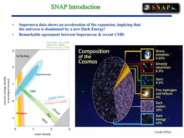
SNAP Introduction • Supernova data shows an acceleration of the expansion, implying that the universe is dominated by a new Dark Energy! • Remarkable agreement between Supernovae & recent CMB. Credit STScI
Theoretical Questions • “Our main achievement in understanding dark energy is to give it a name” – Michael Turner • “In string theory, to get > 0 but extremely small is impossible” - Ed Witten “Would be number one on my list of things to figure out” - Edward Witten “Right now, not only for cosmology but for elementary particle theory this is the bone in the throat” - Steven Weinberg • What is the Nature of the dark energy? • Largest component of our universe • Theory proposes a number of alternatives each with different properties we can measure. • What is the evolution and fate of the universe? “Maybe the most fundamentally mysterious thing in basic science” - Frank Wilczek “This is the biggest embarrassment in theoretical physics” - Michael Turner
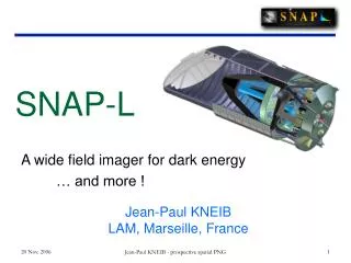
Mission Design SNAP a simple dedicated experiment to study the dark energy • Dedicated instrument, essentially no moving parts • Mirror: 2 meter aperture sensitive to light from distant SN • Photometry: with 1°x 1° billion pixel mosaic camera, high-resistivity, rad-tolerant p-type CCDs and, HgCdTe arrays. (0.4-1.7 mm) • Integral field optical and IR spectroscopy: 0.4-1.7 mm, 2”x2” FOV
What makes the SN measurement special?Control of systematic uncertainties • At every moment in the explosion event, each individual supernova is “sending” us a rich stream of information about its internal physical state. Lightcurve & Peak Brightness Images M and L Dark Energy Properties Redshift & SN Properties Spectra data analysis physics
From Science Goalsto Project Design Science • Measure M and • Measure w and w (z) Systematics Requirements Statistical Requirements • Identified and proposed systematics: • Measurements to eliminate / bound each one to +/–0.02 mag • Sufficient (~2000) numbers of SNe Ia • …distributed in redshift • …out to z < 1.7 Data Set Requirements • Discoveries 3.8 mag before max • Spectroscopy with S/N=10 at 15 Å bins • Near-IR spectroscopy to 1.7 m • • • Satellite / Instrumentation Requirements • ~2-meter mirror Derived requirements: • 1-square degree imager • High Earth orbit • Spectrograph • High bandwidth (0.4 m to 1.7 m) • • •
SAGENAP (2000) • Science review by SAGENAP of 260-page proposal, March 2000. • DOE support commenced after SAGENAP • Study phase (effort to develop CDR, cost, schedule, key technologies).
R&D Review • Recent DOE/Science & R&D Review (Jan 2001): • “SNAP is a science-driven project with compelling scientific goals.” • “SNAP will have a unique ability to measure the variation in the equation of state of the universe.” • “We believe that it is not an overstatement to say that the Type Ia supernova measurements will uniquely address issues at the very heart of the field…” [Implications for string theory] • Issues Raised at R&D Review: • Look at greatly increasing the near-infrared capabilities • Is the proposed IR spectrograph throughput adequate? • Look at a descoped instrument complement: Can the spectroscopy be done by ground-based facilities? • Develop a calibration strategy and plan. • Address NASA relationship
Today’s Talk: Status of R&D • Science Requirements Definition • Monte Carlo Event Generator • Lightcurve generator and fitter • Cosmology fitter • SNe Modeling • Optical Telescope • Optical Design/Layout • Optical Quality • Technology • Stray Light • Thermal Design • NASA IMDC/ISAL Studies • Spacecraft Packaging • Mass & Power • Attitude Control/Pointing • Launch Vehicle • Orbit • Instrumentation • Camera • Survey Strategy • CCD Detectors • Radiation Damage • NIR Detectors • Spectrograph
Tools for Requirements Definition Monte Carlo implements detailed list of systematics Event generator - Create an object list with fluxes. Ingredients: Supernova types, Type Ia subclasses Galactic, host, and gray dust Gravitational lensing Host galaxy properties Image simulator and SN extraction - Measure photometry, spectra from images Data simulator - Generated calibrated light curves and spectra S/N calculated based on observatory parameters Calibration errors Detection efficiency - Measure contamination of non SNe Ia and Malmquist bias Light curve and spectrum fitter - Simultaneously fit key parameters of SN and dust Cosmology fitter - Determine best fit cosmological and dark energy parameters
Simulation Studies Suite Modeling + Theory To probe dark energy, follow SN to z 1.5 -- optimal redshift range, SN distribution, priors Refinement of observational requirements space from -- SN observations/templates:rise time, line widths/shifts, UV -- SN explosion modeling: progenitor, C/O, kinetic energy, metallicity Study of deep, wide field surveys -- advanced exposure time calculations -- dithering, sampling, pixel strategies Gravitational lensing corrections in data analysis -- cross correlate SNAP weak lensing map with SN amplification -- direct fit of microlensing amplification distribution peak and tail
Current Optical Configuration • Annular Field TMA • Prolate ellipsoid concave primary mirror, 2 meter diameter • Hyperbolic convex secondary mirror • Flat oval 45degree folding mirror feeds transverse rear axis • Prolate ellipsoid concave tertiary mirror • Flat focal plane • Delivers < 0.04 arcsecond FWHM geometrical blur over annular field 1.37 sqdeg • Effective focal length 21.66m; f/10.8 final focus • Provides side-mounted detector location for best detector cooling
OTA geometrical ray traceTMA62 configuration Compare Airy disk 26 microns FWZ diameter at 1 micron
OTA Technologies • Existing technologies are suitable for SNAP Optical Telescope Assembly • New materials, processes, test & evaluation methods are unnecessary • Mirror materials • Corning ULE glass: extensive flight history, but expensive • Schott Zerodur glass/ceramic composite: lower cost, widely used in ground based astronomical telescopes, higher mass optic; huge industrial base • Astrium/Boostec SiC-100: newcomer; unproven in space optics; higher CTE; adopted for Herschel/FIRST in infrared • Structural materials • M55J carbon fiber + cyanate ester resin; epoxy adhesive bonds • Mirror finishing technology • conventional grind/polish/figure using abrasives • ion-beam figuring available from two vendors • Mirror surface metrology • same as other space telescopes, e.g. cassegrains • standard interferometer setups will do the job for SNAP • no unusual accuracy drivers have been encountered
OTA THERMAL • KEY DESIGN FEATURES • High Earth orbit (HEO) to minimize IR Earth-glow loads • GaAs cell - OSR striping of the (hot) solar array panels • Front surface heat rejection OK • Optical Solar Reflectors are back silvered Quartz tiles (a ~ 8%, e ~ 80%) • Low emissivity silvered mirrors • Thermal Isolation mounting and MLI blanketing OPTICS: Build,Test, & Fly Warm… like Hubble !
Optical Telescope Assembly (OTA) TMA-62 Optical Prescription TMA-62 LIGHT PATH- primary- secondary- folding flat- tertiary- Giga-Cam- Spectrometer • add PASSIVE 140K CAMERA DEWAR
Optical Telescope Assembly (OTA) • add SECONDARY STRUCTURE low CTE - GFRP • add OPTICAL BENCH low CTE - GFRP • add “OPTICS COFFIN” BELOW low CTE - GFRP- WITH THREE STIFF METERING TUBES
Optical Telescope Assembly (OTA) • add STRAY LIGHT SECONDARY “LAMPSHADE” • add STRAY LIGHT PRIMARY “STOVEPIPE” • add PASSIVE GIGA-CAM RADIATOR • enclose OPTICS COFFIN • add CCD FRONT END ELECTRONICS
Optical Telescope Assembly (OTA) • add THERMALLY ISOLATED SOLAR ARRAY PANELS • add STRAY LIGHT BAFFLE(s)
Optical Telescope Assembly (OTA) • add EXTERNAL MLI THERMAL BLANKETS • add GENERIC SPACECRAFT
NASA GSFC/IMDC Spacecaft Packaging Secondary Mirror and Active Mount Optical Bench Primary Mirror Solar Array Wrap around, body mounted 50% OSR & 50% Cells Thermal Radiator Sub-system electronics Detector/Camera Assembly Propulsion Tanks from GSFC - IMDC study
IMDC Baseline Configuration • ROM MASS: 700 kg (instrument); 500 kg (bus); 250 kg (hydrazine) • ROM POWER: 250 w (instrument); 250 w (bus) • MOSTLY GENERIC SUBSYSYEMS • EPS (electrical), C&DH (command & data handling), Thermal • MISSION UNIQUE SUBSYSTEMS • ACS (attitude control), SMS (structure & mechanisms), Comm • Evolving Bus Configuration Notes • 3-axis stabilized, 4+ Reaction wheels, tactical IRUs, no torquer bars • Sun side w/ isolated body mounted solar arrays & anti-sun side radiators • Standard Hydrazine propulsion system, ~100 kg to raise perigee, ~10 kg/yr for station keeping, ~ 100 kg for Post Mission Disposal • 2 Tbits SSR storage for imaging & spectroscopy data. (Avg. data rate ~52 Mbps; lossless compression plus overhead). • High speed Ka band down link near perigee @ 300 Mbps to Northern Latitude ground station (Berkeley).
ACS Driving Requirements • Pointing Accuracy • Yaw & Pitch : 1 arc-sec (1) • Boresight Roll: 100 arc-sec (1) • Attitude Knowledge • Yaw & Pitch : 0.02 arc-sec (1) • Boresight Roll: 2 arc-sec (1) • Jitter/Stability -Stellar (over 200 sec) • Yaw & Pitch : 0.02 arc-sec (1) • Boresight Roll: 2 arc-sec (1) • Sun Avoidance - VERY RELIABLE SAFE HOLD ! • Earth Avoidance (mostly in orbit choice) • Moon Avoidance (mostly in orbit choice)
ACS Issues and Concerns from IMDC • Jitter • Isolate fundamental wheel frequency through detailed analysis from manufacturer • Must tune wheel isolators - type, size and interface • Flexible Mode Analysis • Require extensive analysis to avoid control/structure resonance • Solar Wind Tipping, given the Large Baffle Cp-Cg offset • Smaller offset will minimize thruster firing frequency and propellant required for daily momentum unloading (est. 30 Nms wheels) • 3 Pointing jitter values • Use current Star tracker with a very accurate Kalman Filter • Augment Star Tracker data with instrument data (on focal plane guider) for fine pointing • May need to replace gyro with SKIRU-DII • Use of Instrument guide data • Possible mitigation by use of more sophisticated focal plane-sensors
Launch Vehicle Study Atlas-EPF Delta-III Sea Launch
Orbit Optimization • High Earth Orbit • Good Overall Optimization of Mission Trade-offs • Low Earth Albedo Provides Multiple Advantages: • Minimum Thermal Change on Structure Reduces Demand on Attitude Control • Excellent Coverage from Berkeley Groundstation • Outside Outer Radiation Belt (elliptical 3 day - 84% of orbit) • Passive Cooling of Detectors • Minimizes Stray Light Chandra type highly elliptical orbit Lunar Assist orbit
Ground Station Coverage Orbit perigee remains over Berkeley for 3 years without adjustment. 6 hour ground pass over Berkeley
Camera Assembly GigaCam Shield Heat radiator
GigaCAM GigaCAM, a one billion pixel array • Approximately 1 billion pixels • ~140 Large format CCD detectors required, ~30 HgCdTe Detectors • Smaller than H.E.P. Vertex Detector (1 m2)
Goals already met Quantum efficiency from 350 nm to 1000 nm. Dark current Read noise CTE for variety of pixel sizes Proton radiation tolerance 60Co radiation tolerance Commercialization of fabrication process Active projects Intrapixel response Device thinning at commercial foundry Packaging for ground based observatories Multistage outputs Readout electronics specification and technology assessment Future work Backup plans for device thinning Further rad hardening by defect engineering SNAP design optimization Number of pixels Pixel size Thickness Output MOSFET structure SNAP specific packaging Design of integrated electronics running cold adjacent to CCDs LBNL CCD R&D Status
High-Resistivity CCD’s • New kind of CCD developed at LBNL • Better overall response than more costly “thinned” devices in use • High-purity silicon has better radiation tolerance for space applications • The CCD’s can be abutted on all four sides enabling very large mosaic arrays • Measured Quantum Efficiency at Lick Observatory (R. Stover):
LBNL CCD’s at NOAO Science studies to date at NOAO using LBNL CCD’s: • Near-earth asteroids • Seyfert galaxy black holes • LNBL Supernova cosmology Cover picture taken at WIYN 3.5m with LBNL 2048 x 2048 CCD (Dumbbell Nebula, NGC 6853) New instrument at NOAO available in shared risk mode using LBNL CCD’s – Multi-Aperture Red Spectrometer (MARS) LBNL CCD’s scheduled for 37 nights during 2002A (Jan – July 2002) See September 2001 newsletter at http://www.noao.edu
Radiation Damage: Comparison to Conventional CCDs CTE is measured using the 55Fe X-ray method at 128 K. 13 MeV proton irradiation at LBNL 88” Cyclotron Degradation is about 110-13 g/MeV. SNAP will be exposed to about 1.8107 MeV/g (solar max). [1]L.Cawley, C.Hanley, “WFC3 Detector Characterization Report #1: CCD44 Radiation Test Results,” Space Telescope Science Institute Instrument Science Report WFC3 2000-05, Oct.2000 [2] T. Hardy, R. Murowinski, M.J. Deen, “Charge transfer efficiency in proton damaged CCDs,” IEEE Trans. Nucl. Sci., 45(2), pp. 154-163, April 1998