Download

1 / 78
780 likes | 792 Views
Chapter 7 – Counters and Registers. Chapter 7 Objectives. Selected areas covered in this chapter : Operation & characteristics of synchronous and asynchronous counters. Analyzing and evaluating various types of counters. Schemes used to decode different types of counters.

E N D
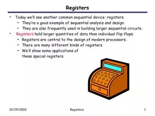
Chapter 7 Objectives • Selected areas covered in this chapter: • Operation & characteristics of synchronous and asynchronous counters. • Analyzing and evaluating various types of counters. • Schemes used to decode different types of counters. • Counter circuits using different levels of abstractionin HDL. • Operation of various types of IC registers. • Shift registers and shift register counters using HDL. • Troubleshooting techniques used for combinational logic systems to troubleshoot sequential logic systems.
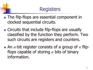
7-1 Asynchronous (Ripple) Counters • Review of four bit counter operation: • Clock is applied only CLK input to FF A. • J & K are HIGH in all FFs. • Output of FF A is CLK of FF B, etc. • FF outputs D, C, B, and A, are a 4-bit binarynumber with D as the MSB.
An asynchronous counter—state is notchanged in exact synchronism with the clock. 7-1 Asynchronous (Ripple) Counters • Review of four bit counter operation: • After the NGT of the 15th clock pulse, the counter FFs are recycled back to 0000.
Adding FFs will increase the MOD number. 7-1 Asynchronous (Ripple) Counters – MOD Number • MOD number is equal to the number of statesthe counter goes through before recycling.
Output frequency of the last counter FF will be clock frequency divided by MOD of the counter. 7-1 Asynchronous (Ripple) Counters – MOD Number • Frequency division – each FF will have an output frequency of 1/2 the input.
7-1 Asynchronous (Ripple) Counters – Signal Flow • Schematics are normally drawn from left to right. • Counters will be drawn from right to left so that the MSB and LSB appear in the appropriate positions.
7-2 Propagation Delay in Ripple Counters • Ripple counters are simple—requiring the fewest components to produce a given operation. • Cumulative propagation delay can cause problemsat high frequencies. • If the period between input pulses is made longer than the total propagation delay of the counter, problems can be avoided • For proper operation: Tclock Nxtpd • Maximum frequency: Fmax=1/Nxtpd
7-2 Propagation Delay in Ripple Counters • Asynchronous counters are not useful at very high frequencies—especially for counters with large numbers of bits. • Erroneous count patterns can generate glitches • Signals produced by systems using asynchronous counters.
Synchronous counters can operate at muchhigher frequencies than asynchronous counters. 7-3 Synchronous (Parallel) Counters • In synchronous or parallel counters, all FFs are triggered simultaneously (in parallel) by the clock.
The total propagation delay will bethe same for any number of FFs. 7-3 Synchronous (Parallel) Counters • Each FF has J & K inputs which are HIGH only when outputs of all lower-order FFs are HIGH.
7-3 Synchronous (Parallel) Counters For this circuit to count properly, on a given NGT of the clock, only those FF that are supposed to toggle on that NGT should haveJ = K = 1 when NGT occurs.
7-4 Counters with MOD Number <2N • The basic synchronous counter shown is limitedto MOD numbers that are equal to 2N. • Where N is the number of FFs.
7-4 Counters with MOD Number <2N 7-4 Counters with MOD Number <2N • The basic counter can be modified to produce MOD numbers less than 2N. • By allowing the counter to skip states that are normally part of the counting sequence. MOD-6 counter produced by clearing a MOD-8counter when a count of six (110) occurs.
7-4 Counters with MOD Number <2N • Changing the MOD number. • Find the smallest MOD required so that 2N is lessthan or equal to the requirement. • Connect a NAND gate to the asynchronous CLEAR inputs of all FFs. Determine which FFs are HIGH at the desired count and connect the outputs of these FFs to the NAND gate inputs.
There is no arrow to the 111 state as the counter can never advance to that state. The 111 state can occuron power-up when the FFs come up in random states. 7-4 Counters with MOD Number < 2N 7-4 Counters with MOD Number <2N State transition diagram for the MOD-6 counter Each circle represents one ofthe possible counter states. Arrows indicate how one state changes to another—in responseto an input clock pulse.
7-4 Counters with MOD Number < 2N 7-4 Counters with MOD Number <2N Display of counter states is often done with an LED The MOD-6 counter lights the LED on HIGH output.
Any MOD-10 counter is a decade counter. 7-4 Counters with MOD Number <2N • Decade counters are widely used for counting events, and displaying results in decimal form. • A decade counter is any counter with 10 distinct states, regardless of the sequence. • A BCD counter is a decade counter that counts from binary 0000 to 1001.
7-4 Counters with MOD Number <2N Mod-60 Counter
7-5 Synchronous Down and Up/Down Counters • A synchronous down counter is constructed in a similar manner to an up counter. • It uses the inverted FF outputs to control the higher-order J, K inputs. Synchronous, MOD-16, down counter and output waveforms.
7-5 Synchronous Down and Up/Down Counters • In a parallel up/down counter, the control input controls the values fed to the J and K inputs ofthe successive FFs. • The normal FF outputs or the inverted FF outputs.
For the first five clock pulses, • The counter counts up. Up/Down = 1. • For the last five pulses, • The counter counts down. Up/Down = 0. 7-5 Synchronous Down and Up/Down Counters
7-5 Synchronous Down and Up/Down Counters • Note that there are two arrows leaving each state’s bubble—a conditional transition. The next state for this counter is dependent uponthe logic level applied to the control input.
Parallel data inputs Synchronous counter with asynchronous parallel load. 7-6 Presettable Counters • A presettable counter can be set to any desired starting point—synchronously or asynchronously. • Preset is also called parallel loading the counter.
7-7 IC Asynchronous Counters Counter contains four FFs. FFs are triggered by a PGTat the CLK input. Active-low asynchronous CLEAR input. Can be preset to any value byapplying an active-low LOADinput to the A, B, C, and D inputs .
7-7 IC Asynchronous Counters This series of IC counter chips has one more output pin—RCO—an active-HIGH output is to detect (decode) the last or terminalstate of the counter. Very useful in connecting twoor more counter chips in a multistage arrangement tocreate larger counters.
7-7 IC Asynchronous Counters TTL 74ALS160 – 74ALS163 Function Table
7-7 IC Asynchronous Counters 74ALS190 and 74ALS191 series ICsare recycling, four-bit counters.
7-7 IC Asynchronous Counters • Many standard IC counters have been designed to make it easy to connect multiple chips to create circuits with a higher counting range. • A multistage or cascading arrangement. 74ALS163s in a two-stage arrangement to extend the maximum counting range.
Active-HIGH decoder output. The LED method becomes inconvenient as thesize (number of bits) of the counter increases.It is much harder to decode the display mentally. 7-8 Decoding a Counter • Digital counters are often used in applications where the count represented by FF states must somehow be determined or displayed. • One of the simplest means for displaying contentsof a counter is connecting the FF output to an LED.
7-8 Decoding a Counter • Decoding is the conversion of a binary output toa decimal value—a form immediately recognized. • The active-HIGH decoder shown can be used to light an LED representing each decimal number 0 to 7.
7-8 Decoding a Counter • Decoding is the conversion of a binary output toa decimal value—a form immediately recognized. MOD-8 Active-HIGH decoder output.
The decoder outputs now produce a normally HIGH signal, which goes LOW only whenthe number being decoded occurs. 7-8 Decoding a Counter The active-HIGH decoder shown canbe changed to an active-LOW type. Active-LOW decoding is obtained byreplacing the AND gates with NAND gates.
7-8 Decoding a Counter • A BCD counter has 10 states, decoded to provide 10 outputs corresponding to decimal digits 0 – 9. • Represented by the states of the counter FFs. • The 10 outputs can control 10 individual indicator LEDs for a visual display. Instead of 10 separate LEDs, BCD counters usually have their count displayed ona single display device.
Control input expressions. 7-9 Analyzing Synchronous Counters Synchronous up counter.
Control input expressions. 7-9 Analyzing Synchronous Counters • Synchronous counters can be custom-designedto generate any desired count sequence. Synchronousup-counter.
7-9 Analyzing Synchronous Counters • Analyze counter designs of this type by predictingFF control inputs for each state of the counter. • A PRESENT state/NEXT state table is very useful for this purpose.
Highlighted information indicates this counterdesign is self-correcting. 7-9 Analyzing Synchronous Counters Synchronous up counter statetransition diagram and waveform.
Control circuitry will typically be more complex than an equivalent JK-type counter, The number of synchronous inputs to controlis reduced by half 7-9 Analyzing Synchronous Counters Synchronous counter built using D-type FFs.
7-10 Synchronous Counter Design • Common design method using J-K flip-flops ina synchronous counter configuration. • Determine the desired number of bits (FFs) and the desired counting sequence. • Draw the state transition diagram showing all possible states—including those not part of the desired counting sequence. • Use the state transition diagram to set up a table that lists all PRESENT states and their NEXT states. • Add a column for each J and K input & indicate levels required to produce transition to the NEXT state. • Design the logic circuits to generate levels required at each input, and implement the final expressions.
7-10 Synchronous Counter Design • A stepper motor rotates in steps, not continuous motion—typically 15 degrees per step. • A practical application of synchronous counter design. • Reversible, depending on output level.
7-10 Synchronous Counter Design • A stepper motor rotates in steps, not continuous motion—typically 15 degrees per step. • A practical application of synchronous counter design. • Reversible, depending on output level.
A full-featured MOD-16 up/down counter. 7-11 Altera Library Functions for Counters • The Quartus Block Editor can program a PLD with any counter using flip-flops and gates. • These macro-functions are in the maxplus2 library.
7-11 Altera Library Functions for Counters Digital clock hours counter—block diagram, MegaWizard settings & simulation results.
7-12 HDL Counters • Methods to describe counter circuits using HDL primarily use synchronous techniques. • All flip-flops update simultaneously in response tothe same clock event. • All bits in a count sequence go from their PRESENT state to their prescribed NEXT state simultaneously, • State Transition Description Methods • The PRESENTstate/NEXT state table is the equivalent of the truth table.
7-12 HDL Counters • State descriptions in AHDL • The first important step is to declare the counter output pins properly— as a bit array.
The current state of the counter is evaluated (count[ ].q)on line 11, and if it is less than the highest desired countvalue, it uses the description count[ ].d count.q + 1 (line 12). 7-12 HDL Counters • State descriptions in AHDL
When the counter has reached the highest desired state(or higher), the IF statement test will be false, resulting in aNEXT-state input value of zero, which recycles the counter. 7-12 HDL Counters • State descriptions in AHDL
7-13 Wiring HDL Modules Together • Designing large digital systems is much easier if the system is subdivided into smaller, manageable modules that are interconnected. • The essence of the concept of hierarchical design. • Consider a recycling, MOD-100 BCD counterwith a synchronous clear. • Creating a MOD-10 BCD counter module, cascading synchronously two of thesein a higher-level designfile is the easiest way to do this.