Download
1 / 13
140 likes | 154 Views
MAXIM Periscope Module. Instrument Systems Engineering Deborah Amato 25 April 2003. X. Z. A Pair of MAXIM Periscopes. 2. 3. Detector. 1. 4. Periscope Module. Launch Configuration. 1 Detector spacecraft 26 Periscope spacecraft for 1000 cm 2 of collecting area:

E N D
MAXIM Periscope Module Instrument Systems Engineering Deborah Amato 25 April 2003
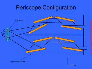
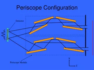
X Z A Pair of MAXIM Periscopes 2 3 Detector 1 4 Periscope Module
Launch Configuration • 1 Detector spacecraft • 26 Periscope spacecraft for 1000 cm2 of collecting area: • 25 free-flyers with 4 periscopes each • 1 hub with 12 periscopes Hub and Detector spacecraft stacked Free-flyer Launch fairing envelope
X Yaw Roll Pitch Z=LOS Y Periscope Coordinate System
MAXIM Periscope Requirements • Low mass and power • Mounted mirror surface quality = rms for = 1 • Difference in entrance and exit mirror-pair spacing, h • Optical Path Difference between periscopes, OPD < lx-ray/10 = 1Å • Relative Strehl ratio > 80% • Position Tolerances – next slide • Must be able to open and close periscope aperture • Must be able to align images on the detector plane • MAXIM Mission Periscope Parameters for this study • Periscope spacecraft swarm diameter, D = 1 km* • Focal length, F = 20,000 km* • Mirror length, m = 30 cm • Mirror width = 20 cm • Graze angle, = 1 • Wavelength, = 10Å * different values used in optical analysis
MAXIM Position Tolerancesl=1nm, F=20,000km, D=1km, m=30cm, =1deg, h=1mm
2 3 = 1 h2 h1 1 4 h and OPD – Key Requirements OPD < lx-ray/10
Trade Studies • Mirror width: 2 cm, 10 cm, 20 cm, 30 cm • Need to quantify the flux requirement for initial calibration • Baseline design: 20 cm wide mirrors • Trade mirror size versus number of spacecraft – discussed in Optical Analysis section • Consider 20 cm versus 30 cm wide mirrors in future studies • Mounted mirror surface quality is dependent on graze angle: rms for = 1 rms for = 2 • Chose = 1 for this baseline design • Internal metrology • Baseline design uses absolute position encoders calibrated with lasers in ground testing.
Periscope Power Summary Spacecraft Power Bus Requirement
Future Studies • This study looked at internal periscope issues – periscope to periscope tolerancing issues still need to be addressed. • Look at operational control and/or mechanical options • Mirror width • 2 cm width feasible? • 30 cm width versus fewer spacecraft • Mirror material is a factor in this trade (silicon vs. ULE) • Further thermal and mechanical design optimization should be done. • See other subsystem presentations for other potential issues.
Up Next • Dennis Evans will discuss the optical analysis next.