Download
1 / 23
230 likes | 238 Views
MAXIM Periscope Module. Structural Analysis Jeff Bolognese 25 April 2003. Structural Analysis Outline. Structural Analysis Goals Finite Element Models Analysis Results Issues and Future Work Conclusions Detailed Analysis Results Mirror Analyses Thermal Deformation

E N D
MAXIM Periscope Module Structural Analysis Jeff Bolognese 25 April 2003
Structural Analysis Outline • Structural Analysis Goals • Finite Element Models • Analysis Results • Issues and Future Work • Conclusions • Detailed Analysis Results • Mirror Analyses • Thermal Deformation • 20g Quasi Static Load Stresses • Optical Bench Analyses • Normal Modes Analysis • Thermal Distortion • Gravity Loading • 1 DOF Actuation
Analysis Goals • For Mirror and Mount • Mass properties of lightweight ULE mirror • Fixed base dynamics assessment • Minimize thermal deformations of mirror surface • Ti stresses < yield for 20g loading • ULE stresses small for 20g loading • For Optical Bench • Fundamental Frequency > 50 Hz • Sensitivity of bench to thermal distortion • Gravity sag distortions • Bench distortions due to 1 DOF actuator actuation • Material trade studies
Finite Element Models • MSC/NASTRAN format • Optics model • ULE used for detailed optics model • 3.5mm face sheet • 2.5mm back sheet • 1.27mm thick core • 20mm cell size (from vertex to vertex) • Ti for flexures • Analysis mass of optic = 2.1 Kg • Optical bench model • Titanium for mounts and flexures • Invar for bench • Lumped masses for optics • Simplified representation of optics mounts • 2D representation of 3d bench • Plate elements with bars for stiffeners • Analysis mass = 68.8 Kg
Mirror FEM Mirror Face Mirror Back 3pt Ti Flexure Mount Optic w/Face Sheet Removed
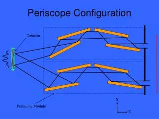
Optical Bench FEM “Daughter” Benches Main Bench Fixed Mount Flexure Simplified Optics Mounts
Mirror Analysis Summary 1cZ Mirror Deformations (mm) 20gY Mirror Back Stresses (MPa) Mirror First Mode = 278 Hz
Optical Bench Analysis Summary Deformation Due to 1c Y Gradient Deformation Due to 1g Z Deformation Due to Single Actuation
Issues and Future Work • Further optimization of bench design is necessary to minimize weight and increase fundamental frequency • Better understanding of thermal environment to quantify allowable material CTE • More detailed modeling of the mirrors and mounts necessary to understand overall mount stiffness as well as quantify local stresses and deformations • Interfaces between mount and mirror will require specific attention • More detailed analysis of “daughter” bench flexures to balance stiffness vs. potential to impose distortions to benches during 1 DOF actuations • Preliminary analyses show coupling between actuations and bench distortions which could complicate control of optics pointing • Better understanding of which displacements of optics can be corrected by mechanisms is needed to be folded into analysis efforts. Calculated displacements should then be considered to determine if, for flight load cases, mechanisms have the range to correct the errors. • More detailed, 3D model of bench is required to fully capture thermal deformations and the complexities of optical mount interfaces when predicted flight loads are applied. • Quantify jitter sources and verify that they are not pose a pointing issue due to dynamic coupling with structure.
Conclusions • Proposed design looks promising but requires further analysis to verify that thermal control is adequate and mechanisms robust enough to correct for launch shifts and on-orbit transients. • Still lots of analysis work to be done!
Backup Slides TBD
Mirror and Mount ThermalDeformations Plot showing Z translations of mirror surface (in mm) after rigid body motion effects are removed 1c Bulk Temp Increase 1c X Gradient 1c Y Gradient 1c Z Gradient
Mirror and Mount 20g Stresses 20 G Y Loading 20 G X Loading 20 G Z Loading Mirror Back Stresses (in MPa) Mirror Flexure Stresses (in MPa)
Optical Bench Fixed Base Dynamics Bench Mode 1 – 49 Hz Bench Mode 3 – 65 Hz Bench Mode 2 – 56 Hz
Bench 1g X Deformations 1g X Deformed Plot
Bench 1g Y Deformations 1g Y Deformed Plot
Bench 1g Z Deformations 1g Z Deformed Plot
.001mm Motion of +Z Side Daughter Board Actuator Deformation Due to .001mm Y Motion of +Z Side Actuator
.001mm Motion of -Z Side Daughter Board Actuator Deformation Due to .001mm Y Motion of -Z Side Actuator
.001mm Motion of Both Daughter Board Actuators Deformation Due to .001mm Y Motion of Both Actuators